Download
1 / 16
160 likes | 331 Vues
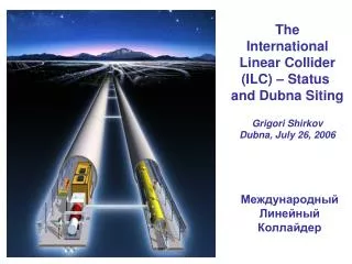
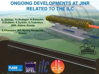
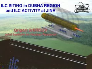
ILC SITING in DUBNA REGION and ILC ACTIVITY at JINR Grigori SHIRKOV Joint Institute for Nuclear Research. PRECISION TERASCALE PHYSICS AT ILC. The electromagnetic and nuclear forces unify at the Terascale.

E N D
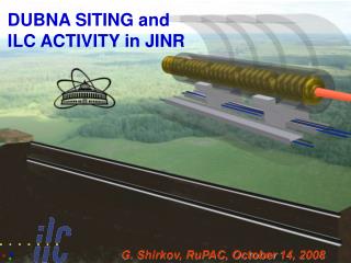
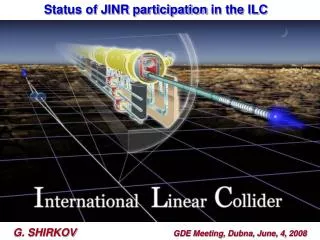
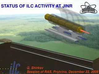
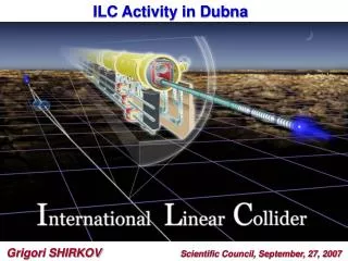
ILC SITING in DUBNA REGION and ILC ACTIVITY at JINR Grigori SHIRKOV Joint Institute for Nuclear Research
PRECISION TERASCALE PHYSICS AT ILC The electromagnetic and nuclear forces unify at the Terascale. The final scientific goals of ILC as well as the time schedule of construction will be accomplished in concert with physical achievements at LHC as well as at other accelerator and nonaccelerator experiments including neutrinos, astrophysics and etc.
Milestones of ILC activity at JINR Nov 2005PAC Particle Physics Proposal about ILC sitting near Dubna Jan 2006JINR Scientific Council Recommended participation in ILC siting Mar 2006Committee of Plenipotentiaries Approved the SC recommendation Nov 2006GDE, Valencia Dubna site was approved as candidate Apr 2007Moscow region Governor Supported JINR initiative Jun 2008Dubna European GDE and ILCS Conference Dec 2008GSPI (Project Institute) Preliminary field engineering-geological investigation along supposed ILC route 2010 – 2011 Moscow State University of Civil Engineering (MSUCE) Graduate works on the ILC siting near Dubna Basic GDE Reports 2007Reference Design Report RDR-2007 2009 Straw-man Baseline Report SB2009 2011 Technical Progress Report IR-2011
WHY TDR in 2012 ?(B.Barish, GDE) The R&D program is effectively ballistic at this point and slowing it down is not cost effective. Synergy with the CLIC CDR (in 2011) Available for the European Strategy for Particle Physics (2012) consideration Ready on a time scale consistent with the first LHC physics results TDR can serves as a basis for value engineering and industrial tech transfer programs Project Implementation Plan available for potential hosts
Detail of the geological cut for the Dubna sample site together with soil boring profiles • drilling of 3 wells in depth of 36.0-47.0 m with full core extraction; • selection of 40 monoliths of soil, 16 samples of disturbed soil for laboratory analysis; • selection of 10 probes of ground water for chemical analysis; • gamma-ray logging, thermometry, vertical seismic profiling, surface seismic survey • 35 points of vertical electric sounding; The obtained data (geological structure and hydro-geological conditions, geotechnical soil properties, etc.) are favorable for placing the linear collider in the investigated territory. The results contained in the GSPI Soil Boring Report supports the positioning of a site that is compatible with the current ILC criteria in the Dubna area and supports a near surface design solution. A. V. Kurnaev et. al. Report on the Results of the Preliminary Geological Engineering Surveys Along the Supposed Route of the International Linear Collider (ILC) in Taldom Area of the Moscow Region, GSPI, Moscow
IDENTIFICATIN OF OPTIMAL ILC LOCATION AND INTERACTION POINT 1st Stage ~32 km 2x500 GeV 2nd Stage ~50km 2x1TeV • JINR Plans with GDE and GSPI for the next years: • analysis of Life Safety in • the tunnel • detailed cost estimation • participation in TDR • preparation
Advantages of the ILC construction in Dubna: • • JINR as a basic scientific and organizational structure with international intergovernmental organization. • • Prevalent legal practice makes it possible to get the land of the ILC location to permanent free use just as it has been done for JINR, according to the agreement between JINR and the RF government. • • The proposed territory is extremely thinly populated and free of industrial structures, rivers and roads. • • The area is absolutely steady seismically and has stable geological characteristics. • • A flat relief and geological conditions allow to place ILC on a small depth (about 20 m) in the dry drift clay and to perform construction of tunnels, experimental halls and other underground objects with the least expenses, including cut-and-cover. • • Sources of the electric power of sufficient capacity: transmission line of 500 kV, the Konakovo electric power station and the Udomlia atomic power plant. • • The developed system of transport and communication services, good highways and railways, water-way (the Volga river basin). • • Presence of a modern network and information infrastructure, including one of the largest center in Europe the “Dubna” Satellite Communication Center. • • A special the economic zone in Dubna provides preferential terms for development and manufacture of high technology technical production. • • A powerful scientific and technical potential of Dubna makes it possible to involve additionally specialists from world scientific centers into the international collective of highly-qualified scientific manpower. • • The only one shallow tunnel with accelerator structures and communication gallery on the surface
THE ILC CRYOMODULES DESIGN&ALIGNMENTJ. Budagov for JINR/ILC team Telescopic collimating unite Prism tube This picture shows the experimental set up used for laser ray space uncertainly σT(L) measurement laser DPH Transparent glass windows This figure demonstrates a unique laser beam space uncertainty σT(L) ) reached when beam passed inside a tube with ends covered by glass windows This figure shows an impressive gain R=σB(L)/σT(L) in beam position precision σT(L) in comparison to the σB(L) at “no tube“ case The principal scheme of a high precision metrology laser complex we used in our studies is shown below. JINR principal investigator - Mikhail Lyablin
PARTICIPATION IN THE ILC CRYOMODULE DESIGN The world first four samples of the Nb-SS joints were made in Sarov in 2010. Samples were researched and tested in Dubna, Sarov and Pisa. The metallographic analysis did not reveal any structural anomalies of the welded components: in the narrow Nb–SS contact zone 0.2÷0.25 mm wide microrigidity of ≈ 4.4 GPa arises. The leak rate measured in Sarov was ≈ 7.5∙10−10 Torr∙l/s. After thermal cycling and exposure to ultrasound in Pisa the upper limit of the leak rate for all test joints was found to be ≈ 2.3÷3.8∙10-10 Torr∙l/s. Leak measurements in FNAL did not show leaks at the detector sensitivity ≈ 7.5∙10−11 Torr∙l/s after six thermal cycles in liquid nitrogen. JINR in collaboration with RFNC (Sarov), INFN (Pisa) and FNAL are working on designing the fourth-generation cryomodule for the ILC. The problem to be solved was to join the helium supply pipe made of stainless steel (SS) and the helium Dewar vessel made of titanium (Ti). Ti and SS cannot be welded together by conventional welding methods. A technology for making a bimetallic Ti+SS tube transition element by the explosion welding method has been developed and implemented for the first time. Yu.Budagov et. al. JINR Preprint E13-2009-25
TESLA-TYPE CAVITY Yu.Budagov, N. Azaryan, D. Demin In 2010 the JINR, BSU, FNAL, INFN collaboration started the experimental study aimed at obtaining a superconducting Nb-cavity in the frame of ILC cryomodule R&D work. The electromagnetic calculations for 1.3 GHz single-cell cavity were fulfilled. We used different simulation tools and the resultsfit each other. Shop-drawings of the cavity and requirements specification for its manufacturing have been issued - cavity profile - electric field on beam axis - electric field on cavity wall - magnetic field on cavity wall
SINGLE CELL CAVITY JINR, FNAL, BSU Firing-Pin Fluid NbPlate Matrix One unit of the composed single-cell cavity was delivered from FNAL to JINR and later it was sent to Belarus colleagues to be used as an “reference unit” in the R&D work. Requirements specification for hydraulic punch-free stamping of the half-cells and its welding on the Belarus equipment have been issued. Measurement techniques of the cavity’s electrodynamics characteristics are investigated. Requirements specifications on stands for cryogenic & RF tests are prepared. • Future Plans: • 9-cell cavity calculations and design; • - calibration tests of the FNAL cavity to adjust the BSU experimental methods and equipment; • - manufacturing & tests of the single-cells.
HOLLOW PHOTOCATHODE CONCEPT FOR E-GUN M.Nozdrin et al., Proceedings of RuPAC-2010 The new concept is proposed: hollow photocathode transparent for the laser beam cathode made like a washer with the width of 4-6 mm with a cone or cylinder aperture in the middle. Work surface of the photocathode is the cone (or cylinder) generatrix. In the case of a cone obliquity is 1:50. Outcome diameter is ~2 mm. Backside irradiation radically simplifies laser beam targeting on emitting surface, accelerator equipment adjustment and allows photocathode work surface laser cleaning. Preliminary emission characteristics of photocathode (Nb, Ø10 mm disk 1 mm thick, normal hade) investigations were done. Radiant flux density (intensity) was changed from 0.8 MW/cm2 to 4.1 MW/cm2 for unfocused beam and from 3.2 MW/cm2 to 16.4 MW/cm2 for focused beam, cathode surface was laser cleaned. During unfocused beam irradiation up to obtainable intensity no thermoemission was observed. Investigations have shown that hollow photocathode usage radically simplifies laser beam targeting on emitting surface, accelerator equipment adjustment and allows photocathode working surface laser cleaning. Quantum efficiency of investigated hollow photocathodes is at least ten times more than QE of solid ones. E-gun with hollow photocathode (back view)
JINR in collaboration with IAP RAS constructed unique laser drive system for STF (KEK) photoinjector The laser system meets the ILC requirements; One macro-pulse contains 2625 micro pulses with 364ns bunch spacing; The macropulse is repeated in 5Hz; The micro-pulse energy is 1.9μJ, which corresponds to 4.3nC assuming 1.0% quantum efficiency of cathode. During system commissioning at KEK our IAP RAS colleagues
HIGH AVERAGE POWER LASER GENERATING ELECTRON BEAM IN ILC FORMAT FOR KEK-STF M.Kuriki et al., Proceedings of IPAC’2010 To provide ILC format beam for Super-conducting Test Facility (STF) at KEK (Japan), an electron source based on photo-cathode L-band RF gun was developed. The laser system for this source consists from Yb fiber oscillator, macro-pulse profiler, Nd:YLF amplifier and Harmonic Generations. The laser system is initially developed IAP (Nizhny Novgorod, Russia) in collaboration with JINR and moved to KEK-STF, Japan for the experiment. Aim of STF at KEK is demonstrating technologies for International Linear Collider (ILC). In STF, one full RF unit, which is composed from one klystron, three Cryomodules, and 24 RF cavities, will be developed and beam acceleration test will be made. It was confirmed that the system performance meets the basic requirements as the driver for the STF photo-cathode injector. Currently, the laser is a stand-alone system and any synchronization to master signal is not implemented at all. The laser system meets the basic ILC requirements: one macro-pulse contains 2439 micro pulses with 369ns bunch spacing; the macro-pulse is repeated in 5Hz; the micro-pulse energy is 1.9μJ, which corresponds to 4.3nC assuming 1.0% quantum efficiency of cathode.Synchronization to master RF signal is easily made by a phase-lock loop with the signal of PMO measured by Photo-Diode, which is already in use and the fast control by the piezo cylinder. STF will perform the beam acceleration test in 2012. Function of Macro-Pulse Profiler. (a) pulse picking, (b) macro pulse forming, and (c) amplitude modulation. For each figures, left side and right side show input and output signals, respectively
Photoinjector test-bech at LHEP JINR (N.Balalykin, V.Kobets) Injector runs are carried out at rating value of the e-gun accelerating voltage (400kV). Design value of the accelerated electronic bunch (6 MeV, 30 mA) is received on 11.11.2011. It is collected and has passed vacuum tests waveguide a path of rf system of first two accelerator stations. Vacuum pressure 8•10^-8 Torr (corresponds to design requirements) is achieved. Tests of power supplies of the focusing coil and heater of the cathode klystron "VARIAN" are carried out. Electric installation of the modulator is finished. The klystron cooling system is mounted under the time circuit
SUMMARY The JINR is carrying out active work to develop international cooperation in the ILC project and in the related projects XFEL and CLIC. The scientists from JINR participate in all international forums and committees on the ILC. JINR has successfully organized wide cooperation in Russia in order to perform experimental and theoretical investigations on the project with Russian research centers (BINP of Siberian Brunch of RAS, Institute for Applied Physics, GSPI, Physical Institute of RAS etc.), JINR Member States and other countries Institutions. THANK YOU FOR ATTENTION