Download
1 / 47
470 likes | 494 Vues
Explore the history and advancements in gravitational wave detection using interferometers. Learn about the sources, limitations, and noise reduction techniques in this cutting-edge field.

E N D
Detection of Gravitational Waves with Interferometers Three generations of instruments Nergis MavalvalaMITMarch 2004
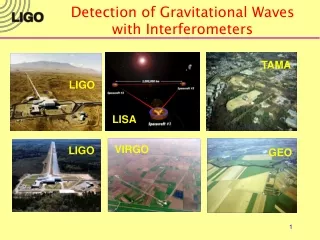
Global network of detectors GEO VIRGO LIGO TAMA AIGO LIGO • Detection confidence • Source polarization • Sky location LISA
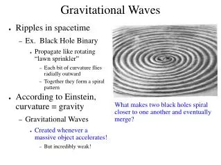
Gravitational Waves • General relativity predicts transverse space-time distortions propagating at speed of light • In TT gauge and weak field approximation, Einstein field equations wave equation • Conservation laws • Conservation of energy no monopole radiation • Conservation of momentum no dipole radiation • Lowest moment of field quadrupole (spin 2) • Radiated by aspherical (“dark) astrophysical objects • Push freely floating masses together and apart
Astrophysics with GWs vs. E&M • Very different information, mostly mutually exclusive • Difficult to predict GW sources based on EM observations
Emission of gravitational radiation from PSR1913+16 due to loss of orbital energy period sped up 14 sec from 1975-94 measured to ~50 msec accuracy deviation grows quadratically with time Nobel prize in 1997 Taylor and Hulse Gravitational waves measured?
R M M r h ~10-21 Strength of GWs:e.g. Neutron Star Binary • Gravitational wave amplitude (strain) • For a binary neutron star pair
Measurement and the real world • How to measure the gravitational-wave? • Measure the displacements of the mirrors of the interferometer by measuring the phase shifts of the light • What makes it hard? • GW amplitude is small • External forces also push the mirrors around • Laser light has fluctuations in its phase and amplitude
GW detector at a glance L ~ 4 km For h ~ 10–21 DL ~ 10-18 m Seismic motion -- ground motion due to natural and anthropogenic sources Thermal noise -- vibrations due to finite temperature Shot noise -- quantum fluctuations in the number of photons detected
Initial LIGO Sensitivity Goal • Strain sensitivity < 3x10-23 1/Hz1/2at 200 Hz • Displacement Noise • Seismic motion • Thermal Noise • Radiation Pressure • Sensing Noise • Photon Shot Noise • Residual Gas • Facilities limits much lower
3 0 3 ( ± 0 1 k 0 m m s ) LIGO WA 4 km 2 km LA 4 km
Limiting Noise Sources:Seismic Noise • Motion of the earth few mm rms at low frequencies • Passive (and active) seismic isolation • amplify at mechanical resonances • but get isolation above 10 Hz (0.10 Hz)
damped springcross section Seismic Isolation • Cascaded stages of masses on springs (same principle as car suspension)
FRICTION Limiting Noise Sources: Thermal Noise • Suspended mirror in equilibrium with 293 K heat bath akBT of energy per mode • Fluctuation-dissipation theorem: • Dissipative system will experience thermally driven fluctuations of its mechanical modes: • Low mechanical loss (high Quality factor) • Suspension no bends or ‘kinks’ in pendulum wire • Test mass no material defects in fused silica Z(f) is mechanical impedance (loss)
Optics Suspension andControl • Suspension is the key to controlling thermal noise • Magnets and coils to control position and angle of mirrors
Core Optics Installation and Alignment • Cleanliness of paramount importance
Limiting Noise Sources: Optical Noise • Shot Noise • Uncertainty in number of photons detected a • Higher circulating power Pbsa low optical losses • Frequency dependence a light (GW signal) storage time in the interferometer • Radiation Pressure Noise • Photons impart momentum to cavity mirrorsFluctuations in the number of photons a • Lower input power, Pbs • Frequency dependence a response of mass to forces Optimal input power depends on frequency
Light bounces back and forth along arms ~100 times 20 kW DL = h L h ~ 10-21 Light is “recycled” ~50 times 300 W input test mass GW Interferometer end test mass Laser + optical field conditioning signal 6Wsingle mode 4 km All cavities on resonance interferometer is “locked”
Stabilized Laser Custom-built 10 W Nd:YAG laser — Now a commercialproduct Stabilization cavities and servo loops
LIGO Optics Substrates: SiO2 • High purity, low absorption • f = 25 cm, mass = 10.8 kg Polishing • Accuracy < 1 nm • Micro-roughness < 0.1 nm Coating • Scatter < 50 ppm • Absorption < 0.5 ppm • Uniformity <10-3 (~1 atom/layer) Industrial partnerships • 2 manufacturers of fused silica • 4 polishers • 5 metrology companies/labs • 1 optical coating company
S2 2nd Science Run Feb - Apr 03 (59 days) S1 1st Science Run Sept 02 (17 days) Strain (1/rtHz) LIGO Target Sensitivity S3 3rd Science Run Nov 03 – Jan 04 (70 days) Frequency (Hz) Science Runs and Sensitivity DL = strain x 4000 m 10-18 m rms
LIGO Science Has Started • LIGO has started taking data • Science runs (S1, S2, S3) • Inspirals reach > few Mpc • Stochastic background limits on Wgw < 10-2 • Periodic sources limits on hmax ~ few x 10-23(e ~ few x 10-6 @ 3.6 kpc) • Reach design sensitivity • Advanced LIGO
The next-generation detectorAdvanced LIGO (aka LIGO II) • Now being designed by the LIGO Scientific Collaboration • Goal: • Quantum-noise-limited interferometer • Factor of 15 increase in sensitivity • Factor of 3000 in event rate One day > entire2-year initial data run • Schedule: • Begin installation: 2007 • Begin data run: 2009
Quantum LIGO I LIGO II Test mass thermal Suspension thermal Seismic A Quantum Limited Interferometer
How will we get there? • Seismic noise • Active isolation system • Mirrors suspended as fourth (!!) stage of quadruple pendulums • Thermal noise • Suspension fused quartz; ribbons • Test mass higher mechanical Q material, e.g. sapphire; more massive (40 kg) • Optical noise • Input laser power increase to ~200 W • Optimize interferometer response signal recycling
Cavity forms compound output coupler with complex reflectivity. Peak response tuned by changing position of SRM ℓ Reflects GW photons back into interferometer to accrue more phase SignalRecycling Signal-recycled Interferometer 800 kW 125 W signal
Advance LIGO Sensitivity:Improved and Tunable broadband detunednarrowband thermal noise
Thorne… Advance LIGO: Source specific
GW signal in the phase quadrature Not true for all interferometer configurations Detuned signal recycled interferometer GW signal in both quadratures Orient squeezed state to reduce noise in phase quadrature X- X- X- X+ X- X+ X+ X+ Squeezed input vacuum state in Michelson Interferometer
Ponderomotive squeezing Vacuum state enters anti-symmetric port Amplitude fluctuations of input state drive mirror position Mirror motion imposes those amplitude fluctuations onto phase of output field X- X+ Input vacuum state gets squeezed in an interferometer X- X+
X- X+ Sub-quantum-limited interferometer Quantum correlations Input squeezing
LISA Laser Interferometer Space Antenna
Laser Interferometer Space Antenna (LISA) • Three spacecraft • triangular formation • separated by 5 million km • Formation trails Earth by 20° • Approx. constant arm-lengths • Constant solar illumination 1 AU = 1.5x10⁸ km
Gravitational-waves Instruments Tests of General Relativity Quantum Measurement Astrophysics
Ultimate success…New Instruments, New Field, the Unexpected…
Production of squeezed light • Non-linear crystals • Optical Parametric Amplification (OPA) • Three wave mixing • Pump (532nm) • Seed (1064nm)
OPA Process • Phase dependent • Lines of force • Compresses along phase axis • Stretches along amplitude axis
GWs neutrinos photons now Analysis working groups Sources • Inspiral • Coalescing compact binaries • Periodic • Periodic continuous waves • Burst • Triggered • Untriggered • Stochastic • Primordial Big Bang background • Continuum of sources