Download
1 / 33
330 likes | 497 Vues
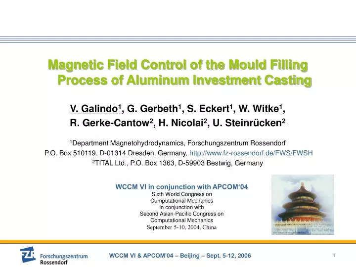
Magnetic Field Control of the Mould Filling Process of Aluminum Investment Casting V. Galindo 1 , G. Gerbeth 1 , S. Eckert 1 , W. Witke 1 , R. Gerke-Cantow 2 , H. Nicolai 2 , U. Steinrücken 2 1 Department Magnetohydrodynamics, Forschungszentrum Rossendorf

E N D
Magnetic Field Control of the Mould Filling Process of Aluminum Investment Casting V. Galindo1, G. Gerbeth1, S. Eckert1, W. Witke1, R. Gerke-Cantow2, H. Nicolai2, U. Steinrücken2 1Department Magnetohydrodynamics, Forschungszentrum Rossendorf P.O. Box 510119, D-01314 Dresden, Germany, http://www.fz-rossendorf.de/FWS/FWSH 2TITAL Ltd., P.O. Box 1363, D-59903 Bestwig, Germany WCCM VI in conjunction with APCOM‘04 Sixth World Congress on Computational Mechanics in conjunction with Second Asian-Pacific Congress on Computational Mechanics September 5-10, 2004, China
Magnetic Field Control of the Mould Filling Process of Aluminum Investment Casting • Overview • Motivation – Aluminum investment casting as example of applied electro-magneto-hydrodynamics • Measuring Techniques in liquid metals • Numerical simulations – “volume of fluid method (VOF)” • Experiments • Conclusions and remarks
Motivation Aluminum investment casting • casting of complex shapes • the whole casting unit is basically a U-bend with the liquid metal filling channel (down sprue) and the mould being the legs connected by a horizontal channel • the liquid aluminum is exclusively moved by hydrostatic pressure Problem Too high fluid velocities in the early stage of the pouring process entrap bubbles and impurities (first) Solution Damping of the turbulent flow with a d.c. magnetic field
Strategy Magnetic Field Control of the Mould Filling Process of Aluminum Investment Casting • Labor experiments with a “cold” liquid metal -Flow observation, velocity measurements- Numerical simulation- Validation• Extrapolation to industrial scales - Numerical simulation - Magnet system design Experiments with model fluid InGaSn Experiments with Aluminum melt under industrial conditions
Strategy- model experiments - Perspex model down sprue • model fluid: InGaSn, liquid at room temperature • magnetic field: d.c. up to 850 mT • transparent walls: optical access mould model horizontal channel magnet pole shoe
Motivation Why do we need flow measurements in metallic melts? Knowledge about the flow field and the transport properties of the flow Optimization of products, technologies and facilities • better understanding of the process • validation of CFD models • on-line control and monitoring
Measuring Techniques Current situation Commercial measuring techniques for liquid metal flows are almost not available! Reasons • properties of the fluid (opaqueness, heat conductivity,..) • high temperatures • chemical reactivity • interfacial effects • external electromagnetic fields
Measuring Techniques List of measuring techniques • Local probes (invasive) • Electric Potential Probe (EPP, Vives Probe) • Mechano-Optical Probe (MOP) • Ultrasonic methods (non-invasive, but need contact) • Ultrasound Doppler Velocimetry (UDV) • Inductive methods (contactless) • Inductive Flowmeter (IFM) • Tomographic Inductive Velocity Reconstruction (TIVR) • X-ray radioscopy
Measuring Techniques Ultrasound Doppler Velocimetry (UDV) • Takeda (1987, 1991) • Commercial instrument • standard transducers (Tmax = 150°C) • Measurement of instantaneous velocity profiles
Measuring Techniques Ultrasound Doppler Velocimetry (UDV)– measuring principle - Pulse-echo method: • information about the position time of flight measurement • information about velocity Doppler relation (c - sound velocity, fD - Doppler frequency, f0 - ultrasound frequency)
Measuring Techniques Ultrasound Doppler Velocimetry (UDV) UDV in liquid metals - current situation • UDV is considered as very attractive for measurements in opaque fluids • successful measurements have already been published for mercury at room temperature (Takeda 1987, Takeda et al. 1998) gallium T = 30...60°C (Brito et al. 2001) sodium T = 150°C (Eckert&Gerbeth 2002) PbBi, CuSn T = 620°C (Eckert et al. 2003) aluminium T = 800°C (Eckert et al. EPM2003)
Measuring Techniques Inductive Flowmeter (IFM) • Measurement of the perturbation of the magnetic field by the flow • voltage is proportional to the flow rate • high temporal resolution • can be applied at high temperatures G: geometry factor
Numeric Simulation • momentum conservation: time dependent Navier–Stokes equation with Lorentz force density term • mass conservation: (non-dimensional)Governing equations I where is the Reynolds number and is the electromagnetic interaction parameter. is the density, is the dynamic viscosity, is the electric conductivity, B0 is a characteristic magnetic field strength, L is a characteristic length and v0 is a characteristic velocity.
Numeric Simulation (non-dimensional)Governing equations II In the case of a present static magnetic field it is necessary to solve an additional equation for the electric potential • electric charge conservation:taking into account the Ohm‘s and Kirchhoff‘s law, following equation for the electric potential holds: • boundary conditions: isolating walls, non-slip
Numeric Simulation Material properties – characteristic numbers The system is defined through 2 independent non-dimensional characteristic parameters: Re and N taking L=0.03 m (channel height), v0=0.5 m/s and B=0.5 T we obtain:
Numeric Simulation • finite element code FIDAP: solution of the Navier-stokes equation for the flow and, in the case of applied static magnetic fields, an additional „species“ equation for the electrical potential Φ • 4 nodes (2d) or 8 node (3d) per element, bilinear interpolation • segregated algorithm for coupled equation system • volume of fluid (VOF) method for simulation of the filling process – void fraction is a new unknown scalar • 2 turbulence models: Prandtl mixing length hypothesis and standard k-ε Sketch of the volume of fluid (VOF) method Interface: surface with a given constant value of the void fraction
Numeric Simulation Application of a static magnetic field down sprue Electromagnetic force density acts as damping force mould model z y x pole shoes geometry sketch computational grid
3D-Numeric Simulation with the VOF Method Application of a static magnetic field Attenuation of the maximal velocity value at the beginning of the filling process t = 0.15 s B = 0 T B = 0.5 T Velocity vector plot on a cut plane in horizontal channel. Vmax=1.25 m/s corresponds to colorred
3D-Numeric Simulation with the VOF Method Application of a static magnetic field t = 0.25 s B = 0 T B = 0.5 T Velocity vector plot on a cut plane in horizontal channel. Vmax=1.25 m/s corresponds to colorred
3D-Numeric Simulation with the VOF Method Application of a static magnetic field t = 0.5 s B = 0 T B = 0.5 T Velocity vector plot on a cut plane in horizontal channel. Vmax=1.25 m/s corresponds to colorred
3D-Numeric Simulation with the VOF Method Application of a static magnetic field t = 0.75 s B = 0 T B = 0.5 T Velocity vector plot on a cut plane in horizontal channel. Vmax=1.25 m/s corresponds to colorred
3D-Numeric Simulation with the VOF Method Application of a static magnetic field t = 1 s B = 0 T B = 0.5 T Velocity vector plot on a cut plane in horizontal channel. Vmax=1.25 m/s corresponds to colorred
3D-Numeric Simulation with the VOF Method Application of a static magnetic field Simulation with the help of the VOF (“volume of fluid”) method; Video left: without right: with magnetic field video shows the first 2.5 seconds of the filling process B=0.5T B=0T
Experiments One of the most dangerous stage of the pouring process Production of swirl in the beginning of the pouring process with high probability of bubble entrapment
Experiments UDV velocity measurement in the model experiment in the down sprue channel in the down horizontal channel • dangerous peak velocity in the early stage removed • velocity fluctuations become smaller
Experiments Velocity measurements obtained at a pouring experiment with a) InGaSn at room temperature b) AlSi alloy at about 700°C
Experiments Validation of the numerical simulation Comparison of numerical and experimental results regarding the flow rate Q as a function of the magnetic field strength (related to the flow rate obtained at B = 0)
Al casting Experiments Casting units evaluation Visual inspection of the resulting metal surface UV-light visualization of surface defects B=0.25 T B=0.75 T in the first 5 seconds 07.06.2014 07.06.2014
Al casting Experiments Casting units evaluation - Statistics Clear tendency: the d.c. magnetic field always lead to an improved quality of the casting unit with reduced amount of entrapped oxides
Conclusions I • Velocity and flow rate measurements are needed for better understanding of the flow phenomena and filling process of the investment casting of Al • Low temperature metallic melt InGaSn has been used for model experiments; key advantage: at this temperature a sufficient number of different measuring techniques are available • Validation of numerical codes using such liquid metal models provides a profound basis for an extrapolation of the numerics to the real scale problem and turned out to be essential for the reliable simulation of the real Al casting process • Main problem in the pouring process: the occurrence of large velocity values at the beginning of the casting processes leads to an accumulated generation of vortices inside the pouring channel
Conclusions II • A high rate of turbulences in the flow is supposed to entail the transported impurities, oxides or gas bubbles from the walls and the free surface into the bulk of the casting patterns. As a result the mechanical properties are deteriorated • The external d.c. magnetic fielddamps the high flow velocities at the beginning of the pouring process. A significant reduction of the peak velocities, leading to a generation of vortices inside the pouring channel, has been shown by model experiments and numerics, and has been demonstrated in the real Al casting process afterwards • As a important input for the control system, a contact-less flow rate sensor has been developed and successfully applied • The statistics of a multitude of cast units showed a clear tendency of reduced oxide entrapment due to the magnetic field influence
Perspective • Next step: linear a.c. traveling field which breaks initially, and pumps in the end constant flow rate during the whole process Induced electromagnetic force density compute with a finite element Maxwell solver OPERA Scheme of the coil system to generate the traveling magnetic field
Thank you for your attention ! Vladimir Galindo Forschungszentrum Rossendorf Inc. P. O. Box 510119, 01314 Dresden Germany galindo@fz-rossendorf.de http://www.dresden.com http://www.fz-rossendorf.de