Download
1 / 8
80 likes | 200 Vues
This document discusses the complexities involved in computing Time-of-Flight (TOF) parameters from Time-to-Digital Converter (TDC) data across multiple chambers. It explores how factors like clock phase differences, track curvature, and cable lengths affect time measurements. This analysis incorporates various parameters, including T0 corrections and drift times, crucial for accurate event reconstruction in particle physics. By simulating realistic conditions in data analysis, the document aims to improve precision in TOF measurements necessary for high-energy physics experiments.

E N D
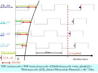
Clk_ch4 Clk_ch3 Clk_ch2 Clk_ch1 TOF (ch, track) 25 ns L1A _ch 0 Absolute time t L1A global T0+T0r TDC (ch,layer,cell) = TOF (track,ch,layer,cell) +[Tdrift(ch,layer,cell) +wire_p(trak(j)] + T0(ch,layer,cell)-{[Clk_ch(ch)+T0r(ch,rob)]+ Phase(ch) } +K+ *25ns
What is recorded in the TDC is : TDC (ch,layer,cell) = TOF (trak,ch,layer,cell) +[Tdrift(ch,layer,cell) +wire_p(trak(j)] + T0(ch,layer,cell)-{[Clk_ch(ch)+T0r(ch,rob)]+ Phase(ch) } +K+ *25ns TOF is different from chamber to chamber and from track to track since the path length can be different due to the curvature (momentum and B) and position in the chamber. In principle it can be computed once we have the track parameters. In simulation it is known . Clk_ch(ch) takes into account the possible different clock phase It is fixed and due to ‘cables from the TTRX to the Mini Crate of a chamber ‘. T0r(ch,rob)takes into account the different cables length of the clock distribution to each ROB inside the Mini Crate(there are 7-10 rob/ch and it is 1-2 ns for phi robs and 10 ns for theta robs). Values from the information of the Test Pulses data. T0(ch,layer,cell) contains the behavior of the Front End electronics. Phase(ch) is the delay adjustmentof the clock in each Mini Crate in order to maximize the Local Trigger efficiency. It can vary from run to run ; it is written in the condition Data Base .It is the parameter to be set chamber by chamber and can, in principle, varies ( it depends on the chamber data i.e. HV, gas, etc etc ). K(ch)is a fix number of bx which defines the dimension of the window read out from the tdc data.Only data of the TDC in a defined window ( K++K-*25ns units) around a required bx will be output.
Data analysis: Up to nowwe just used one chamber so ‘TOF - Clk_ch’ was computed directly from the data : it is the T0 computed from the MeanTime and the Time box (see CMS NOTE 2004/001 , CMS NOTE-2003/007 etc). In these data the information were recorded in Caen TDC ; only on the Test Beam 2003 and 2004 we used the Mini Crate read out. In these Test Beam anyway the spot of the beam was very narrow so few elements of the Mini Crate were involved . In the Test Beam 2004 the TOF and the Clk_ch had started to play a role. In the cosmic data at LNL with 2 chamber the Clk_ch , TOF and thewire_propagation(trak(j)) are important. Simulation of the DIGI: Up to now in the simulation it was assumed that each chamber has Clk_ch = TOF of infinite momentum track normal to the chamber So it was simulated a the situation with all the detector already tuned in their best possible shape. That should be correct for physics predictions . But we need these parameters if, with the program of ORCA, we want to simulate real data. If we want indeed to simulate the different conditions of data taken at Test Beam or cosmic ray data and the situation at the magnet test we need to include all the parameter listed above.
Simulation ( new) : TDC (ch,layer,cell) = TOF (ch,layer,cell) - {[Clk_ch(ch) +T0cl(ch,rob) ]}+ +Phase(ch) } + T0(ch,layer,cell) +[Tdrift(ch,layer,cell) +w_delay(trak(j)] +K(ch)*25ns The trigger emulator will use the data information of the TDC subtracting from the data ‘K+ *25ns ‘ and ‘T0cl(ch,rob) ‘ ; the Phase(ch) will be used in the algorithm. The values of ‘T0(ch,layer,cell) + T0cl(ch,rob)’ are computed from the test pulses data ie from TP(ch,layer,cell) . In the DAQ output data format we may see the dependence asTP(DDU,Ros,Rob,tdc#,chan#). The computationof T0cl(ch,rob) can be performed from the dependence of the TP on the DDU,Ros,Rob numbers. Actually from the Test Pulse data collected with the TDC and with the new Mini Crates, the Front End behavior the spread of the T0(ch,layer,cell)is around 1 ns showing that the cabling in the Mini crate is done very accurately. The spread of the T0cl(ch,rob).
Clk_ch4 Clk_ch3 Clk_ch2 Clk_ch1 TOF (ch, track) 25 ns L1A _ch 0 Clk + Phase Clk Phase L1_local Absolute time t T0+T0r TDC (ch,layer,cell) = TOF (ch,layer,cell) +[Tdrift(ch,layer,cell) +wire_p(trak(j)] + T0(ch,layer,cell)-{[Clk_ch(ch)+T0r(ch,rob)]+ Phase(ch) } +K+ *25ns
Drift-time+wirePropagation Clk_ch4 Clk_ch3 Local TS Syncronisation Clk + TS Phase Clk_ ch2 Clk Phase Clk_ch1 25 ns TOF (ch, track) LT_out 0 TS Sector Collector output/ input Track Finder TS LocalTrigger Mini Crate output FE input & BTI ( phase=0)
Drift-time+wirePropagation Clk_ch4 Clk_ch3 Local Trigger Syncronisation Clk + TS Phase Clk_ ch2 Clk Phase Clk_ch1 25 ns TOF (ch, track) LT_out 0 TS Sector Collector output/ input Track Finder TS LocalTrigger Mini Crate output FE input & BTI ( phase=0)
Clk_ch4 Clk_ch3 Clk_ch2 Clk_ch1 TOF (ch, track) 25 ns L1A _ch 0 Absolute time t L1A global T0+T0r TDC (ch,layer,cell) = TOF (track,ch,layer,cell) +[Tdrift(ch,layer,cell) +wire_p(trak(j)] + T0(ch,layer,cell)-{[Clk_ch(ch)+T0r(ch,rob)]+ Phase(ch) } +K+ *25ns