Overview of the L1 Vertex Trigger Project: Architectures and Challenges
Join us for an in-depth exploration of the L1 Vertex Trigger Project presented by M. Koratzinos from CERN. This talk provides a personal and historical overview of the project, its components, planning, and the complex algorithms involved in high-rate event processing. Key topics include architecture design, CPU performance, data management, and the overall system's ability to operate efficiently at luminosity levels of 2x10^32. Discover the challenges faced in real-time data processing and the collaborative efforts required for success in particle physics research.

Overview of the L1 Vertex Trigger Project: Architectures and Challenges
E N D
Presentation Transcript
Vertex TriggerWorkshop Saturday, 14th of November, 1998 The Vertex Trigger Detector Project M. Koratzinos (CERN)
Outline of the talk • A personal and probably biased overview of the project • by someone working on it for the past couple of years. • Historical Overview • Project components • Project planning
ODE board MUX ODE board MUX ... Network Switch SFC ... CPU CPU SFC ... CPU CPU ... SFC ... CPU CPU L1 Global Trigger DAQ LTrg Base line implementation model Transfer all the data fragments of an event to a single CPU and execute the trigger algorithm in software • Key issues: • High rate (1 MHz) • Small data fragments (2kB/event) • Standard CPUs for fast trigger
Data rates & sizes • At nominal luminosity (2x1032): • Rate of single events after L0: 1.0MHz • Rate of double events after L0: 0.2MHz • Average size of event with no noise: 600 clusters • Cluster address length: 2 bytes • Typical noise per event: 200 hits (100-400 hits) • Typical packaging overhead: 250 bytes • Single event size: 1850 bytes (@1.0MHz) • Double event size:3050 bytes (@0.2MHz) • Most probable bandwidth: 2.4GBytes/sec
L1 Algorithm Performance & Latency • Required min. bias event reduction factor: 25 • Signal efficiency @ above reduction factor: ~50% • Maximum latency: 512µs
Past milestones & decisions • Technical Proposal ( Early 1998): • L1 buffers are Digital buffers (large latencies possible) • Baseline solution is the all-software approach chosen in favour of the approach of a mixture of hardware pre-processing /software. • L1 Trigger Workshop (June 1998): • First discussion on project planning & organisation
L1 Vertex Trigger Project 2 5 ODE Control + Monitoring ODE ODE Switch Network 4 L1 specific L1 specific L1 specific CPU farm SFC CPU farm SFC CPU farm SFC CPU farm SFC 1 3 7 6 L1 Global Trigger L1 VTX Local Trigger To DAQ
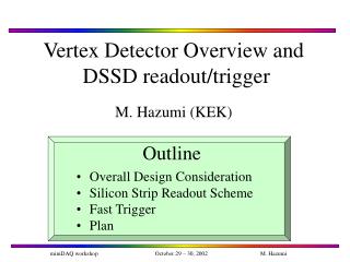
Vertex Detector ODE - L1 specific 1 To L1 Buffer Apply Threshold Pedestal subtraction Common mode correction FADC 40MHz 1 bit From Detector 8 bit 8 bit 8 bit L1 signal processing Clustering Encapsulation Zero suppression To Switch 6 bit 6 bit L1 trigger interface 16 bit
ODE-L1 VTX Possible Implementation One Station ODE Board 64X32 channels L1 Zero suppression + clusterisation + Encapsulation L1 Specific: pedestal +com. mode + threshold To Switch 40MHz 64 X 1bit
Switch Network 2 • The Switch network performs the Event Building • Needs to be able to sustain 2GB/sec • Safety factor of 2 • Need to build a switch able to sustain 4GB/sec • Commercially available or custom made
Sub Farm Controller 3 SFC From Switch CPU CPU CPU CPU To L1 VTX Trig Box To L1 VTX Trigger Monitor • Interfaces to the switch (~2Kbytes@50KHz) • Does Load Balancing • Presents event decisions to the VTX Trig. Box • Interfaces to the control and monitoring task
CPU farm 4 • Total number of processors ~100 • Average execution time ~100µs • Maximum execution time ~400µs • Physics Algorithm execution • Physics performance a lot of work up to TP • Resources utilisation (latency, etc) benchmarks • Exception handling • ...
Control & Monitoring Task 5 • Loading of calibration files • System configuration • Book keeping • Beam movements • Validity of calibration constants • …
L1 VTX Local Trigger Box 6 • Gets decisions from SFCs • Orders decisions • Presents ordered event list to Global L1 Trigger Box • Sends L1 VTX trigger partition data to DAQ • Operating at 1MHz rate
L1 Trigger Box 7 TTC L1 Global Trigger Box L0 Trigger L1 VTX trig L1 TRK Trig DAC L1_YES
Project Planning TODAY LHC starts System Ready
R&D Activities • Trigger algorithm: • Optimization (physics performance, CPU resources). • CPU benchmarks. • Understanding processing time tails. • Check with test-beam data. • System simulation (virtual prototype): • Study performance of different philosophies, strategies & protocols. • Verify system behaviour (buffers, throughputs, CPU allocation) • Obtain component specifications. • Test scalability.
R&D Activities (2) • Evaluation/Study of technologies • Commercial networks & switches (in collaboration with DAQ) • Links, FPGA technology, DSP technology. • Small scale component prototypes: • ODE L1 specific electronics [ODE group] • Trigger decision processor (1 MHz) • Single sub-farm • Commodity CPUs, synchronization, operating system issues, error handling, etc. • Event builder using commercial pieces (L1 requirements). • Verify performance. Error handling.
Conclusions • The L1 Vertex Trigger Project is exiting, diverse and requires competence in many fields: • Physics (algorithm performance) • System Architecture • Electronics design & manufacturing (ODE,SFC,switch, L1VTX trigger box) • Software engineering (algorithm, farm, control&monitoring) • Project well suited for a Consortium of institutes collaborating closely