Download
1 / 47
470 likes | 587 Vues
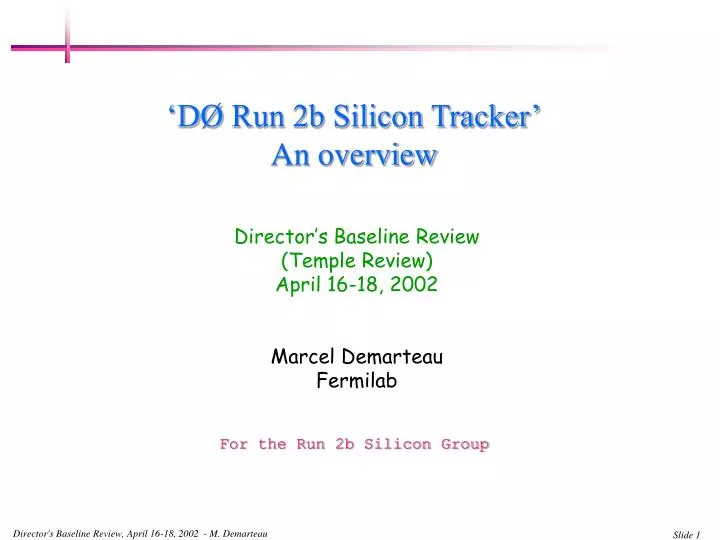
‘D Ø Run 2b Silicon Tracker’ An overview. Director’s Baseline Review (Temple Review) April 16-18, 2002 Marcel Demarteau Fermilab. For the Run 2b Silicon Group. L xy ~ 3 mm. Run2b Focus: Higgs Boson. Production Dominant production channel gg H Overwhelmed by background

E N D
‘DØ Run 2b Silicon Tracker’An overview Director’s Baseline Review (Temple Review) April 16-18, 2002 Marcel Demarteau Fermilab For the Run 2b Silicon Group Director's Baseline Review, April 16-18, 2002 - M. Demarteau
Lxy~ 3 mm Run2b Focus: Higgs Boson • Production • Dominant production channel gg H • Overwhelmed by background • Observable production channel qq WH, ZH • Lepton(s) from W/Z provides trigger • Decay • H coupling proportional to mass • Dominant decay to bbar • Requirements • Excellent b-tagging efficiency • eb > ~65 % per jet at mistag rate < ~1% • Robust silicon tracker • lean but with adequate redundancy Director's Baseline Review, April 16-18, 2002 - M. Demarteau
Outline • Design considerations • Boundary conditions • Space • DAQ constraint • Silicon track trigger • Radiation damage • Brief overview of proposed detector • Anticipated performance • Project overview • Organization • Cost: M&S • Schedule • Resources • Conclusion Director's Baseline Review, April 16-18, 2002 - M. Demarteau
Design Considerations • Do not compromise on the performance of the Run2a silicon tracker • Choose design adequate to achieve physics goals but do not over-design (no 90-degree stereo), • Provide stand-alone tracking up to |h| < 2.0 • Fiber tracker has full coverage only up to |h| < 1.6 • Modular design, minimize the number of different elements • Use established technologies • Use single sided silicon only • Due to harsh radiation environment, divide tracker in two radial groups: • Inner layers • Design to withstand integrated luminosity of 15 fb-1, with adequate margin • Provide path for possible replacement of innermost layers • Outer layers • Design to last a long time Director's Baseline Review, April 16-18, 2002 - M. Demarteau
Boundary Conditions • Spatial • Installation within existing fiber tracker, with inner radius of 180 mm • Installation in collision hall • Tracker will be built in two independent half-modules, split at z=0 • Data Acquisition • Retain all of the downstream readout electronics • Re-use current cable plant • allows for ~912 readout modules • Total number of readout modules cannot exceed 912 • Silicon Track Trigger • Respect 6-fold symmetry Z=0 Director's Baseline Review, April 16-18, 2002 - M. Demarteau
Radiation Damage • Sensors will be subjected to fluence of 2 1014 1 MeV neutron equiv./cm2 • Parameters for detector • Vdepl after irradiation • Signal to Noise ratio • Requirements • S/N ratio > 10 after 15 fb-1 • Vdepl« Vbreak to allow for over-depletion for full chargecollection Layer 0 12.9 fb-1 +10 0C 0 0C Vdepl (V) -10 0C Days Director's Baseline Review, April 16-18, 2002 - M. Demarteau
Basic Layout • Six layer silicon tracker, divided in two radial groups • Inner layers: Layers 0 and 1 • Axial readout only • Mounted on integrated support • Assembled into one unit • Designed for Vbias up to 700 V • Outer layers: Layers 2-5 • Axial and stereo readout • Stave support structure • Designed for Vbias up to 300 V • Employ single sided silicon only, 3 sensor types • 2-chip wide for Layer 0 • 3-chip wide for Layer 1 • 5-chip wide for Layers 2-5 • No element supported from the beampipe • Drilled Be Beampipe with ID of 0.96”, 500mm wall thickness Director's Baseline Review, April 16-18, 2002 - M. Demarteau
Layer 0 • Support Structure • 12-fold crenellated geometry • carbon fiber support • possible use of pyrolitic graphite • sensors cooled to T=-10 oC • Rin = 18.5 mm Silicon Analogue cable Hybrid • Assembly • 2-chip wide sensors • 25 mm pitch, 50 mm readout • Analogue cables for readout • Hybrids off-board • Staggered in z for 6 readouts per end per phi-sector • Space is extremely tight ! Outside tracking volume Director's Baseline Review, April 16-18, 2002 - M. Demarteau
Layer 1 • Support Structure • 12-fold castellated geometry • carbon fiber support • Integrated cooling • sensors cooled to T=-5 oC • Rin = 34.8 mm Cooling lines • Assembly • 3-chip wide sensors, 58 mm pitch, axial readout • Hybrids on-board • 6-chip double-ended hybrid readout Hybrid Silicon L0 Digital cable Full view layer 1 Director's Baseline Review, April 16-18, 2002 - M. Demarteau
Layers 2-5 • 12, 18, 24 and 30-fold geometry • All layers: • Use the same sensor, 5-chip wide sensor, 30 mm pitch, 60 mm readout • Hybrids on-board • 10-chip hybrid readout • Stereo and axial readout • Stereo angle obtained by rotating sensor • Support • Modules are assembled into staves • Staves are positioned with carbon-fiber bulkheads CMS Endplate Director's Baseline Review, April 16-18, 2002 - M. Demarteau
Stave Structure • Stave is doublet structureof four readout modules • Two layers of silicon • Axial and stereo • Two readout modules each • separated by cooling lines • Total of 168 staves • Stave has carbon fiber cover • Protect wirebonds • Provide path for digital cables • Staves are mounted in end carbon fiber bulkheads • Cooling manifold similar to bulkhead design Layer 4-5 stave Director's Baseline Review, April 16-18, 2002 - M. Demarteau
Outer Layer Readout Modules • Staves are assembled from readout modules • Readout modules: • 6 types • 10-10 (axial, stereo) • 10-20 (axial, stereo) • 20-20 (axial, stereo) • Stereo angle determined by mechanical constraints • 10cm readout: a = 2.5o • 20cm readout: a = 1.25o • Ganged sensors will have traces aligned • Module configuration • Each readout module serviced by double-ended hybrid • Each hybrid has two independent readout segments Layer 4-5 20-20 Layer 2-3 10-10 10-20 Director's Baseline Review, April 16-18, 2002 - M. Demarteau
Readout Schematics • Layer 0: due to cooling requirements hybrids off-board • Fine pitch flexible cables to bring analogue signals out of tracking volume • Layers 1-5: Hybrids mounted on silicon; digital cable connects to hybrid • Provides chip control signals • Power for chip and bias voltage • SVX4 chip employed in SVX2 readout mode to readout silicon • MOSIS submission of FE 06/04/01 • MOSIS submission of full chip 03/28/02 • Submission delay of ~5 months; both projects will get about 500 chips from this run • Project assumes in its schedule that second full chip submission is needed • Second submission: October ’02 • Production submission: April ’03; • SVX4 drives the schedule Hybrid Layer 0 AnalogueCable 8’ Twisted Pair Cable Interface with current DAQ system 2’ Digital Cable Junction Card Sensor Layers 1-5 Hybrid Adapter Card Director's Baseline Review, April 16-18, 2002 - M. Demarteau
Testing and Quality Assurance • First pass database exists to track all components for detector • Fields for data entry being defined for first parts received • Sensors, hybrids and cables • Relations for proper queries being defined • Test stands for testing first components being setup at SiDet • Two hybrid burn-in test stands, 16 channels each • Two module burn-in test stands, 32 modules each Devices under test Director's Baseline Review, April 16-18, 2002 - M. Demarteau
Parameters of Proposed Detector • Few Characteristics: • Sensors: 2184; Silicon area of 8.3 m2 • 888 hybrids, i.e readout cables (Run2a: 912) • 7440 SVX4 chips for a total of 952320 channels (Run2a: 792576) Director's Baseline Review, April 16-18, 2002 - M. Demarteau
Performance of Proposed Detector • Performance studies based on full Geant simulation • Full model of geometry and material • Model of noise, mean of 2.1 ADC counts • Single hit resolution of ~10 mm • Longitudinal segmentation implemented • Pattern recognition and track reconstruction • Benchmarks • s(pT)/PT ~ 3% at 10 GeV/c • s(d0)2 = 5.22 + (25/pT)2 • s(d0) < 15 mm for pT > 10 GeV/c 2b 2a Impact Parameter (cm) Director's Baseline Review, April 16-18, 2002 - M. Demarteau
Performance of Proposed Detector • B-tagging • Loose b-tag algorithm: signed impact parameter, Eb > 20 GeV • Track selection • within cone DR < 0.5 of b-jet • pT > 0.5 GeV/c, good c2, hits in silicon 2 • Impact parameter significance • 2 tracks: d0/s(d0) > 3 • 3 tracks: d0/s(d0) > 2 • b-jet tagging efficiency of ~ 65% per jet • Compare to Higgs working group assumptions ET (GeV) Based on WH-events, with b’s falling within acceptance Director's Baseline Review, April 16-18, 2002 - M. Demarteau
SiliconM. DemarteauA. Bean, Deputy MechanicalW. Cooper, K. Krempetz Sensor Accounting, TestingR. Demina, F. Lehner ElectronicsA. Nomerotski, W. Reay ProductionTBA QA, Testing, & Burn-inC. Gerber, TBA Simulation L. Chabalina, F. Rizatdinova Radiation MonitorS. de Jong Organization • Major commitments from various groups • Mechanical design and fabrication • University of Washington: Layer 0, 1 • Sensor Testing • Kansas State University • Stony Brook • Cinvestav, Moscow Stave University • Electronics • Kansas State University • Digital cables; Adapter card, Junction card, Test card • University of Kansas, Fresno University • Hybrid testing • Louisiana Tech • Digital cable testing • QA • UIC, Northwestern University • Monitoring • Radiation monitoring, NIKHEF • Temperature Monitoring, Rice • Trying to strengthen group further Director's Baseline Review, April 16-18, 2002 - M. Demarteau
Cost and NSF Funding • Cost drivers • Silicon sensors • Cables: analogue, digital and twisted pair in near equal amounts • Hybrids • Project has secured Major Research Instrumentation (MRI) Grant from NSF • $1.6M of NSF equipment funds and $800k of Cost Share by participating universities • 10 participating universities; University of Kansas grant administrator Director's Baseline Review, April 16-18, 2002 - M. Demarteau
Approach to Cost Estimate • Strongly relies on Run2a experience • Estimates for assembly, fixturing • Initial quotes for equipment • General philosophy regarding contingency • Uniform 50% • Areas with little experience: 70% • Quote in hand, or previously purchased commercial items: 30% • Spare count part of production cost, never included in contingency • Items already purchased: 0% • MRI contribution • MRI contribution is fixed dollar amount • When identified as such in M&S cost estimate, assumed no contingency • Permits to verify overall level of contingency Director's Baseline Review, April 16-18, 2002 - M. Demarteau
Cost Profile • We are in the process of setting up budget tracking tools • Tracking of MRI and Fermilab encumbrances • Obligations and spending profile match to good degree Sensor purchase Director's Baseline Review, April 16-18, 2002 - M. Demarteau
Schedule • Project broken down in subtasks at level 9 using MSProject • Project resource loaded, manpower estimates follow from resource loading • Broken down into over 800 subtasks • No stand alone tasks; all tasks in reference to successors or predecessors • Some Key tasks: • SVX4 production and testing 4/11/03 – 3/10/04 • Outer layer sensor production and probing 1/21/03 – 5/14/04 • Outer layer hybrid production and testing 6/23/03 – 6/10/04 • Outer layer module production and burn-in 1/14/04 – 8/30/04 • Some key milestones • SVX4 chip released for production 4/11/03 • Last outer layer sensor received 4/30/04 • South silicon complete 11/17/04 • Shutdown starts 3/14/05 • Silicon Ready to move to DAB 5/31/05 • An explicit 8 weeks contingency is built in at the end of the project Director's Baseline Review, April 16-18, 2002 - M. Demarteau
Milestones • Major task have associated milestones, which are evenly distributed in time Director's Baseline Review, April 16-18, 2002 - M. Demarteau
Sensitivity Analysis • Using current schedule, added (equivalent of) third prototype run for various critical items and looked at the effect on the schedule Director's Baseline Review, April 16-18, 2002 - M. Demarteau
Approach to Labor Estimate • Blanket assumption for labor: • 1456 hrs/yr or 364 hrs/quarter, which corresponds to 70% efficiency • 52 weeks/yr * 5 days/week - 39 days vacation, sick, holidays = 221 days, which corresponds to 85% efficiency • Efficiency of use of those available hours 82% (meetings, coffee break, bathroom break, …) • When converting hours of labor into FTE’s, this number is applied • In addition, there’s an efficiency factor folded in task by task • Example: 10-10 axial Module production • Duration: 8 weeks, 2.1 modules/day • Resources: 0.5 CMMT, 0.5 MTF • In production mode, module assembly should take about 1 hour/module • Needs some setup time, cleanup time, and things may go wrong • Manpower estimates come from resource loaded schedule Director's Baseline Review, April 16-18, 2002 - M. Demarteau
Total SiDet Manpower Needs • Comparison of total manpower needs for SiDet where laboratory has given guidance Lab Guidance: 18 FTE’s Director's Baseline Review, April 16-18, 2002 - M. Demarteau
Selected Fermilab Manpower Needs • Projected needs for mechanical engineers and designers Lab Guidance for SiDet: 5 FTE’s • Available manpower for engineers and designers • So far has matched more or less project needs • Worry about second quarter: if not matched, project will fall behind current schedule Director's Baseline Review, April 16-18, 2002 - M. Demarteau
Selected SiDet Manpower Needs • Comparison of technical manpower needs for SiDet where laboratory has given guidance Lab Guidance: 13 FTE’s • Peak production • Really need people with the right skills. Finding people with the right skills has been a problem in the past. We are optimistic that we can try to recruit CMMT’s from the collaboration as was done for Run2a Director's Baseline Review, April 16-18, 2002 - M. Demarteau
Total Fermilab Manpower Estimate • Add all Fermilab manpower and all physicists from Fermilab and Universities Director's Baseline Review, April 16-18, 2002 - M. Demarteau
Concluding Remarks • The Run2b upgrades will allow us to exploit the unique opportunity for discovery available to the Laboratory; however, it is only available within a limited time frame • The silicon detector proposed is well suited to address the physics issues of Run2b • Emphasis on impact parameter measurement at small radii • The design is not overextended • A lot of progress has been made in all areas • Some significant issues and risks remain • Schedule • Manpower needs • Funding • We are looking for your advice and help trying to get the project on a solid footing for a possible future baseline review. Director's Baseline Review, April 16-18, 2002 - M. Demarteau
Nomenclature • MEF Mechanical Engineer, Fermilab • DESF Designer, Fermilab • MTSF Mechanical Technician, SiDet, Fermilab • ETSF Electrical Technician, SiDet, Fermilab • WBNDRT Wirebonder Technician • CMMT Coordinate Measuring Machine Technician • CMMP Coordinate Measuring Machine Programmer • EEF Electrical Engineer Fermilab • MTF Mechanical Technician, Fermilab (non-SiDet) • ETF Electrical Technician, Fermilab (non-SiDet) • COMPF Computing Professional, Fermilab Director's Baseline Review, April 16-18, 2002 - M. Demarteau
Run 2b • Although we just built a major silicon detector, construction of a new silicon detector is planned • Current silicon detector designed for ~ 2 fb-1; will most likely survive 4-5 fb-1 • The most appropriate rad-hard technology used at that time • Laboratory: • Supports extended running to ~ 15 fb-1 / exp • Unique window of opportunity for Fermilab to be the sole laboratory with possibility to find the Higgs boson • Asked both collaborations to study options for replacing Si detectors • Choice of exp’s is full replacement • Suggested a time scale and asked for submission of TDR by fall ’01 • Field of High Energy Physics • Higgs search is highest priority of the laboratory and perhaps the field • LHC: turn on of LHC sets clear end date for window of opportunity Director's Baseline Review, April 16-18, 2002 - M. Demarteau
Overall Plan View Positioning bulkhead Cooling bulkheads Junction cards Director's Baseline Review, April 16-18, 2002 - M. Demarteau
Longitudinal Segmentation • Designed the detector to have uniform coverage in pseudorapidity • Layers 0/1: 6 sensors per half-module; sensor length 79.4 mm • Layers 2/3: stave populated by 5 sensors only; sensor length 100 mm • reduction of sensor count by 120 sensors • Layers 4/5: stave populated by 6 sensors; sensor length 100 mm • Longitudinal segmentation • Determined by • Number of allowed readout cables • Occupancy, cluster sharing • Configuration • L0, L1: each sensor readout • L2, L3: 10-10-10-20 readout • L4, L5: 10-10-20-20 readout • Hybrids are all double-ended • Services two readout segments Z=0 Z (mm) Readout segment # Director's Baseline Review, April 16-18, 2002 - M. Demarteau
SVX4 Chip • Nov ’00 decision to employ common readout chip for CDF and DØ • SVX4 in deep sub-micron, 0.25 mm technology, intrinsically rad-hard • Brand new chip with own personality/features • Commercial foundries used (TSMC) • Test chips • MOSIS submission of FE 06/04/01 • Decided on pre-amp and pipeline design • ENC = 450e + 43.0e/pF (optimum) • MOSIS submission of full chip 03/28/02 • Submission delay of ~5 months • Two versions of chip (same padring) • On chip bypassing employed (DØ) • On chip bypassing not used (CDF) • Both projects get ~300 chips each • Projects need working chips to certify all readout electronics components • Project assumes in its schedule that second full chip submission is needed • Second submission: October ’02 • Production submission: April ’03 • SVX4 drives the schedule LBL Pre-amp Pipeline FNAL Pre-amp Director's Baseline Review, April 16-18, 2002 - M. Demarteau
Sensitivity Analysis • Using current schedule, removed second prototype run for various critical items when appropriate and looked at the effect on the schedule • Close coupling • SVX4 chips and hybrids • Sensors third driving schedule Director's Baseline Review, April 16-18, 2002 - M. Demarteau
MRI Layer 1 sensors ELMA $6.0k Layer 1 sensors HPK $65.0k Standalone Seq. $70.0k Analogue Flex cables Prototype 1 $6.0k Prototype 2 $6.0k Layer 1 hybrids $16.1k Connectors $2.4 Components $1.6 Mexico setup $80.0k Stony Brook setup $80.0k KSU setup $80.0k Mexico HV $200k Expenditures to Date • FNAL • Carbon fiber $5.5k • Digital Jumper Cables • Honeywell $21.5k • Basis Electronics $3.9k • Material $2.0k • Standalone Seq. $10.0k • Layer 1 Hybrids • Layout $2.0k • SiDet CMM $35.0k • SVX4 $54.0k • Beampipe $98k • MRI Matching • UIC $4k • Fresno $7k • KU (Ledford) $10k • KU Logic analyzer $8k • UW $35.5k • Total of ~$910k Director's Baseline Review, April 16-18, 2002 - M. Demarteau
Near Term Start Dates • Complete resource loaded schedule being prepared • Some near term start dates / milestones Submitted to ELMA Ready for submission Director's Baseline Review, April 16-18, 2002 - M. Demarteau
Boundary Conditions: spatial • Silicon tracker to be installed within existing fiber tracker, with inner radius of 180 mm • Full tracking coverage • Fiber tracker up to |h| < 1.6 • Silicon stand-alone up to |h| < 2.0 • Installation in collision hall • Tracker will be split at z=0 • Two independent half-modules • Reproducible mount at z=0 • Alignment verified at SiDet • Installation of beampipe after tracker installation • There will be a 3mm gap from sensor to sensor at z=0 Director's Baseline Review, April 16-18, 2002 - M. Demarteau
Luminous Region • Addresses uncertainty on evolution of beam size over the course of a store • Assumed beam crossing centered at z=0; no uncertainties folded in • Coverage of inner layers of 100 cm results in loss of < ~2% of integrated luminosity • Length of inner layer set at 96 cm • Luminosity acceptance of detector in Run2b running conditions • Longitudinal emittance 2, 3 eV-sec • Stacking rate 40, 60 E10/hr • Assumptions: • b* = 35 cm • Trans. e = 20/15 p.mm.mrad • 0.5 crossing angle 136 mrad From M. Church Director's Baseline Review, April 16-18, 2002 - M. Demarteau
Layer 0 Support Structure • Prototype support structure made by University of Washington • Crenellated mandrel • Stacking sequences • Cylindrical Shell: 3 ply 0º, 90º, 0º laminate • Castellated Shell: 6 ply [0º, +20º, -20º]s laminate • RTV pressure strips, vacuum bag • Pressured to 85 psi • Cured in autoclave at 275 °F castellated shell Measurements and comparisons of elastic properties of prepreg. laminates Director's Baseline Review, April 16-18, 2002 - M. Demarteau
Irradiation Studies • Irradiation studies carried out with ELMA sensors and CDF layer 00 sensors from Hamamatsu and Micron • Measured Ileak, Vdepl • Measurements agree well with other measurements • Calculate Ileak, Vdepl and ENC for various Si temperatures to determine Si running temperature during operation Conclude that the design value for Silicon operating temperature at the inner layer should be T= -10 oC Director's Baseline Review, April 16-18, 2002 - M. Demarteau
2a: Innermost radius 25.7 mm Outermost radius 94.3 mm 2b: Innermost radius 17.5 mm Outermost radius 163.6 mm Comparison 2a and 2b End views drawn to scale Director's Baseline Review, April 16-18, 2002 - M. Demarteau
Sensor Procurement Director's Baseline Review, April 16-18, 2002 - M. Demarteau
Why no 90-degree Stereo • Issues: • Due to multiplexing of signals more difficult pattern recognition; more fakes • Large incident angles, large number of strips hit • Preferentially use thinner silicon to partially compensate • Fraction of tracks that have a close neighbor is rather high • Need to resort to splitting shared clusters • Requires double-metal layer; HPK no experience with dm layers on 6” wafers • No definitive answer yet from Run2a data • We have confidence that we can achieve our physics goals with the current design • Of course, 3d-vertex gives additional information, but has to be compared to additional requirements • Complicates design, more sensor types, more testing, probing, more manpower, … • DØ made conscientious decision not to adopt 90-degree stereo readout given manpower and time constraints Director's Baseline Review, April 16-18, 2002 - M. Demarteau
Director's Baseline Review, April 16-18, 2002 - M. Demarteau
Hybrid AnalogueCable 8’ Twisted Pair Cable Interface with current DAQ system 2’ Digital Cable Junction Card Sensor Hybrid Adapter Card Director's Baseline Review, April 16-18, 2002 - M. Demarteau