Download
1 / 45
450 likes | 572 Vues
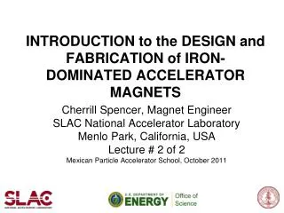
INTRODUCTION to the DESIGN and FABRICATION of IRON-DOMINATED ACCELERATOR MAGNETS. Cherrill Spencer, Magnet Engineer SLAC National Accelerator Laboratory Menlo Park, California, USA Lecture # 2 of 2 Mexican Particle Accelerator School, October 2011. Overview of my Two Lectures, part 1.

E N D
INTRODUCTION to the DESIGN and FABRICATION of IRON-DOMINATED ACCELERATOR MAGNETS Cherrill Spencer, Magnet Engineer SLAC National Accelerator Laboratory Menlo Park, California, USA Lecture # 2 of 2 Mexican Particle Accelerator School, October 2011
Overview of my Two Lectures, part 1 Lecture 1 • Purpose of my lectures on electromagnets • And steps of producing accelerator magnets • How Maxwell’s Equations help us design magnets for particle accelerators • The steps of designing a magnet • Computer modelling to make a detailed design MePAS, Cherrill Spencer, Magnet Lecture #2 Guanajuato. 3rd October 2011
Overview of my Two Lectures, part 2 Lecture 2 • Choice of materials and fabrication techniques • Fabricating steel yoke • Fabricating coils • Assembling the whole magnet, connecting it to power and cooling sources • Testing & magnetically measuring a magnet • Installing magnets in a beamline: alignment • Resources where you can find out much more about accelerator magnets MePAS, Cherrill Spencer, Magnet Lecture #2 Guanajuato. 3rd October 2011
Spencer and quadrupole she helped to design for the ATF2 beam-line at KEK, Japan MePAS, Cherrill Spencer, Magnet Lecture #2 Guanajuato. 3rd October 2011
Review how to calculate amount of current, NI, needed to produce a field B in a quad with steel core Steel core L1 Radius r, of aperture Rewrite the above equation ,using B’ = B Pole Tip /radius =BPT/r NI ≈ BPT r/ 2 µ0 L2 Cross section through part of coil carrying NI ampturns of current How does an ME decide how long L1 and L2 should be?: depends mostly on the properties of the steel the core ; must choose a type of steel that is capable of carrying all the flux coming through from the aperture, without saturating” MePAS, Cherrill Spencer, Magnet Lecture #1 Guanajuato. 1st October 2011
Large selection of magnetic materials shown on a 1955 graph by GE MePAS, Cherrill Spencer, Magnet Lecture #1 Guanajuato. 1st October 2011
Low Carbon Steel typically used in solid steel magnet cores (also called yokes) From years of experience magnet engineers have decided that “low carbon steel” has best magnetic properties for a reasonable price. C1010 has 0.1% carbon, its B-H curve can be altered by annealing after being rolled into plate ~ 12 cm thick by 11m by 6m Hot rolled C1010 steel annealed at 3 different temperatures MePAS, Cherrill Spencer, Magnet Lecture #1 Guanajuato. 1st October 2011
Steel plate can be used as solid pieces or rolled further to make very thin sheets • Low carbon steel plate can be rolled into thin sheets, from 1.5mm to 6mm thick • Typically 1.5mm sheet used in magnets • Shape of one quadrant of a quad core is cut out of sheet by a punch and die operation OR • In past few years: lasers been used to cut out laminations • Which to use depends on way magnet will be operated and relative cost of 2 methods MePAS, Cherrill Spencer, Magnet Lecture #1 Guanajuato. 1st October 2011
Two quadrants of quadrupole core machined from solid low carbon steel MePAS, Cherrill Spencer, Magnet Lecture #1 Guanajuato. 1st October 2011
For a laminated core use a stacking fixture to build up the core MePAS, Cherrill Spencer, Magnet Lecture #2 Guanajuato. 3rd October 2011
Machine stacked quadrants on a planer machine: smooth split planes MePAS, Cherrill Spencer, Magnet Lecture #2 Guanajuato. 3rd October 2011
Finished laminated quadrant & 2 completed quadrupoles ready for installation MePAS, Cherrill Spencer, Magnet Lecture #2 Guanajuato. 3rd October 2011
Accounting for length of core and fringe fields at the ends: effective length Field at ends of magnet decreases gradually and beam particles will continue to feel the field. So must use an effective magnetic length in the integral strength equation. Make approximation to real shape of field: a trapezoid. Figure is for a dipole. Rules of thumb for effective length: Dipole Leff = Lcore + gap Quad Leff = Lcore + aperture radius MePAS, Cherrill Spencer, Magnet Lecture #1 Guanajuato. 1st October 2011
Choose material and shape of the conductor to be wound into a coil Various shapes of hollow copper conductors available. Usually use square outside shape with a round hole down the center where the cooling water “low conductivity water” [LCW] will flow. “Oxygen-free” copper grades offer high electrical and thermal conductivity and their freedom from oxygen ensures excellent brazeability and weldability, making them superior to oxygen-bearing copper grades. MePAS, Cherrill Spencer, Magnet Lecture #1 Guanajuato. 1st October 2011
Insulate the conductor so lengths can be laid next to each other • Two insulating tapes wound around the copper conductor before it is wound into a coil: • 1st layer e.g. Mylar tape 0.076mm thick x 12.7mm wide • 2nd layer e.g. Glass cloth tape 0.178mm thick x 12.7mm • Wind “half-lapped” : 2nd turn of tape around the conductor overlaps half the width of the previous turn of tape • Can have a technician do the wrapping or can invent a clever machine to use the rolls of tape and wrap the tapes • See next photos MePAS, Cherrill Spencer, Magnet Lecture #2 Guanajuato. 3rd October 2011
Spools of hollow copper conductor & set-up to apply insulation tapes MePAS, Cherrill Spencer, Magnet Lecture #1 Guanajuato. 1st October 2011
Can wrap tapes by hand or with automated tape wrapping machine MePAS, Cherrill Spencer, Magnet Lecture #1 Guanajuato. 1st October 2011
Designing a magnet coil; calculate coil resistance MePAS, Cherrill Spencer, Magnet Lecture #1 Guanajuato. 1st October 2011
Magnet design standards & rules • Typical current densities we use in SLAC coils: 5000 to 7500 amps per square inch: • Applying this limit determines number of turns N in a coil, because it limits I – after choosing a conductor size. • Increase in temperature of cooling water to be less than 25 ° C- application of this rule determines how many water circuits to have in a coil • NO internal brazes in a coil – most magnet failures occur at brazes and if inside coil impossible to mend. So continuous conductor between external brazes [-> length of a water circuit] MePAS, Cherrill Spencer, Magnet Lecture #1 Guanajuato. 1st October 2011
Water flow curves showing relations between pressure drop across pipes of various diameters, the volume of water flow per minute and the velocity of the water in the pipe. Based on the Williams and Hazen formula for smooth drawn copper pipes. Sorry, these are in imperial units, tried to make some metric curves: ran out of time MePAS, Cherrill Spencer, Magnet Lecture #2 Guanajuato. 3rd October 2011
Water flow curves showing relations between pressure drop across pipes of various diameters, the volume of water flow per minute and the velocity of the water in the pipe. Based on the Williams and Hazen formula for smooth drawn copper pipes. Sorry, these are in imperial units, tried to make some metric curves: ran out of time MePAS, Cherrill Spencer, Magnet Lecture #1 Guanajuato. 1st October 2011
After engineering details been calculated: work with mechanical designer to draw all parts so can be made Core assembly drawing for a dipole magnet MePAS, Cherrill Spencer, Magnet Lecture #1 Guanajuato. 1st October 2011
Drawing for top coil of dipole magnet MePAS, Cherrill Spencer, Magnet Lecture #1 Guanajuato. 1st October 2011
Assembly drawing for dipole magnet MePAS, Cherrill Spencer, Magnet Lecture #1 Guanajuato. 1st October 2011
Coil winding form and winding operation MePAS, Cherrill Spencer, Magnet Lecture #1 Guanajuato. 1st October 2011
Ingredients of a SLAC potting epoxy used to glue the conductor turns together in a coil COMPONENT. MANUFACTURER. DER332: Diglycidyl Ether of Bisphenyl A Dow Chemical Corp. DER732: Epichlorohydrin-polyglycol reaction product. Dow Chemical . NMA: Nadic methyl anhydride Shell Chemical. BDMA: Benzyl dimethyl amine Lindau Chemicals Z6040: Silane wetting agent Dow Corning Corp. MI Cab-o-Sil: maintains suspension, amorphous SiO2 Cabot Corp. IL Alumina: Al2O3,low iron+ soda,325 mesh, T64 Alcoa, PA *************** Components used in different fractions depending on where the coil will be used. The higher the radiation expected the more alumina one would use. In the ring magnets of a 2-3 GeV storage ring expect little radiation. MePAS, Cherrill Spencer, Magnet Lecture #1 Guanajuato. 1st October 2011
Dipole “racetrack” coil in its potting mold Dipole “racetrack” coil in its potting mold, lid will be added next. Tightened down so mold is vacuum tight. Epoxy will be sucked into the evacuated mold where it will flow between the conductor turns and form an outer layer around the whole coil. MePAS, Cherrill Spencer, Magnet Lecture #1 Guanajuato. 1st October 2011
Typical epoxy potting & curing instructions • Epoxy is a thick but will flow through tubes and into narrow spaces between the turns, getting absorbed into the insulation. Must avoid areas without any epoxy. • Pre-heat the mold and coil to 55°C±5°C prior to introducing epoxy. • The epoxy should be introduced into the mold at ambient temperature. • Raise the temperature slowly from 60°C to 90°C. • Pre-cure for 4 hours minimum at 90°C ±5°C to gel epoxy. • Raise the temperature slowly from 90°C to 130°C. • Cure for 4 hours at 130°C±5°C. • Decrease oven temperature slowly, remove mold from oven while still warm. • Remove coil from mold before reaches room temperature. MePAS, Cherrill Spencer, Magnet Lecture #1 Guanajuato. 1st October 2011
Industrial sized mixing bowls; vacuum tank MePAS, Cherrill Spencer, Magnet Lecture #1 Guanajuato. 1st October 2011
Testing & measuring magnet parts during fabrication [circulate samples to students] Most important to test the various magnet components as they are being made MePAS, Cherrill Spencer, Magnet Lecture #1 Guanajuato. 1st October 2011
Now have the core and coils, been measured & tested, ready to be assembled into whole magnet [sextupole] MePAS, Cherrill Spencer, Magnet Lecture #2 Guanajuato. 3rd October 2011
Completed sextupoles installed in beam-line with orange “Synflex” cooling hoses attached MePAS, Cherrill Spencer, Magnet Lecture #2 Guanajuato. 3rd October 2011
Octupole made from solid steel and solid wire coils MePAS, Cherrill Spencer, Magnet Lecture #2 Guanajuato. 3rd October 2011
Protection against loss of cooling water: thermal switch connected to conductor MePAS, Cherrill Spencer, Magnet Lecture #2 Guanajuato. 3rd October 2011
Typical magnet power supplies- source of current in magnet LH PS: 150 V- 350 A RH PS: 80V- 250 A Controlled by custom made controllers with feedback loops so current stability is 0.01% at worst up to 10ppm for most stable system. Current stability important for all magnets. MePAS, Cherrill Spencer, Magnet Lecture #1 Guanajuato. 1st October 2011
Quadrupole magnet being measured by a “rotating coil” MePAS, Cherrill Spencer, Magnet Lecture #1 Guanajuato. 1st October 2011
Different parts of rotating coil apparatus Multiplexor : takes N input voltages from coil’s windings and sends one output to voltage integrator End of rotating coil where all the wires from the various windings come to terminals MePAS, Cherrill Spencer, Magnet Lecture #1 Guanajuato. 1st October 2011
Schematic of rotating harmonic analysis coil & its voltage signals corresponding to 4 & 12 poles MePAS, Cherrill Spencer, Magnet Lecture #1 Guanajuato. 1st October 2011
Incorrectly assembled quad core & the octupole component created by the offset pole MePAS, Cherrill Spencer, Magnet Lecture #1 Guanajuato. 1st October 2011
Equipment used to find the mechanical center of a magnet and install magnet in the beam-line FARO ARM: portable coordinate measuring machine (CMM). OPTICAL TELESCOPE MePAS, Cherrill Spencer, Magnet Lecture #1 Guanajuato. 1st October 2011
Targets mounted on magnets to be used with the telescopes/laser trackers MePAS, Cherrill Spencer, Magnet Lecture #1 Guanajuato. 1st October 2011
FINAL GOAL ACHIEVED: Dipole magnet successfully installed in a beam-line MePAS, Cherrill Spencer, Magnet Lecture #1 Guanajuato. 1st October 2011
Then an ME goes to a magnet conference and gives a paper on her work & has a nice time! Spencer at International Magnet Technology Conference MT21 in Hefei, China. In world heritage Huangshan Mts MePAS, Cherrill Spencer, Magnet Lecture #1 Guanajuato. 1st October 2011
Very useful books & articles on iron-dominated magnets for those wishing to learn more “Iron Dominated Electromagnets” by Jack T. Tanabe, book published by World Scientific “Iron Dominated Magnets” by G.E. Fischer, SLAC-PUB-3726. Available through SPIRES search engine on the SLAC website MePAS, Cherrill Spencer, Magnet Lecture #1 Guanajuato. 1st October 2011
Homework problem for lecture #2 WILL BE AVAILABLE during this afternoon! Will be posted on the MePAS website MePAS, Cherrill Spencer, Magnet Lecture #1 Guanajuato. 1st October 2011