FOWLER CHAPTER 10 LECTURE 10 CAPACITANCE
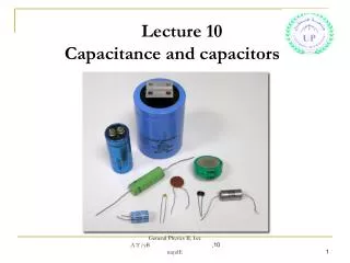
FOWLER CHAPTER 10 LECTURE 10 CAPACITANCE. CAPACITANCE THE STORING OF ENERGY AS ELECTRICAL CHARGE. CAPCITORS STORE ELECTRIC CHARGE. THEY ARE MADE FROM 2 CONDUCTIVE PLATES SEPARATED BY A INSULATOR.(DIELECTRIC). HOW DOES A CAPACITOR WORK? (See figure below)

FOWLER CHAPTER 10 LECTURE 10 CAPACITANCE
E N D
Presentation Transcript
CAPACITANCE THE STORING OF ENERGY AS ELECTRICAL CHARGE. CAPCITORS STORE ELECTRIC CHARGE. THEY ARE MADE FROM 2 CONDUCTIVE PLATES SEPARATED BY A INSULATOR.(DIELECTRIC)
HOW DOES A CAPACITOR WORK? (See figure below) AS BATTERY DISCHARGES, ONE OF THE CAPCITOR PLATES BUILDS UP A NEG. CHARGE WHILE A DIFFICIENCY OF CHARGE BUILDS UP ON THE OTHER PLATE.( POS. CHARGE). WHILE THE CAP IS CHARGING NO ELECTRONS MOVE FROM ONE PLATE TO THE OTHER. WHEN THE CAP IS FULLY CHARGED, ITS VOLTAGE IS EQUAL TO THE BATTERY VOLTAGE THAT CHARGED IT. http://www.youtube.com/watch?v=t9Qwx75eg8w How a Capacitor Works - by Dr. Oliver Winn
THIS CHARGED CAPACITOR(THE ENERGY SOURCE) CAN BE REMOVED FROM THE CHARGING CIRCUIT + + - - IF A LOAD IS PLACED ACROSS IT, THE CAPACITOR WILL RAPIDLY DISCHARGE. + - Charging And Discharging A Capacitor http://micro.magnet.fsu.edu/electromag/java/capacitor/index.html
MAKE presents: The Capacitor http://www.youtube.com/watch?v=ZYH9dGl4gUE
WHY ARE CAPACITORS NOT USED AS ENERGY SOURCES? 1. THEY HOLD A SMALL AMOUNT OF CHAGRE AS COMPARED TO A BATTERY OF SIMILAR WEIGHT. 2. THEIR VOLTAGE RAPIDLY DECREASES AS THE CAPACITOR IS DISCHARGED THRU A LOAD.
ENERGY IS STORED IN THE DIELECTRIC BY STRESS PLACED ON ELECTRONS IN THEIR ORBITAL PATHS.
VOLTAGE RATING OF CAPACITORS. DCWV: DIRECT CURRENT VOLTAGE RATING, RATED MAXINIUM VOLTAGE THAT A CAPACITOR CAN OPERATOR AT WITHOUT BREAKING DOWN. YOU TUBE: Capacitor explosion from excessive voltage http://www.youtube.com/watch?v=_WheLp0RdLQ
UNIT OF CAPACITANCE P.247 CAPACITANCE IS MEASURED IN FARADS. (F) 1 FARAD = 1COULOMB/ 1 VOLT = 1C/1V ONE FARAD IS THE AMOUNT OF CAPACITANCE THAT STORES 1 COULOMB (Q) OF CHARGE WHEN THE CAP IS CHARGED TO 1 VOLT. C = Q/V CAPACITANCE (C) IS USUALLY MEASURED IN MICROFARADS ( uF)
Capacitor Color Code Table Metalized Polyester Capacitors Disc & Ceramic Capacitors
Capacitor Voltage Color Code Table • Capacitor Voltage Reference • Type J - Dipped Tantalum Capacitors. • Type K - Mica Capacitors. • Type L - Polyester/Polystyrene Capacitors. • Type M - Electrolytic 4 Band Capacitors. • Type N - Electrolytic 3 Band Capacitors.
Capacitor Tolerance Letter Codes Table Consider the capacitor below: CAP CODES SEE APPENDIX H
What factors determine the capacitance of a capacitor? 1. Area of the plates 2. Distance between the plates 3. Type of dielectric 4. Temperature.
1. AREA OF THE PLATES: CAPACITANCE IS DIRECTLY PROPORTIONAL TO THE AREA OF THE PLATES. DOUBLE THE AREA , DOUBLES THE CAPACITANCE. WHY? THE AREA OF DIELECTRIC. IS DOUBLED. 2. DISTANCE BETWEEN PLATES: CAPACITANCE IS INVERSELY PROPORTIONAL TO THE DISTANCE BETWEEN THE PLATES. AS DISTANCE INCREASES, CAPACITANCE DECREASES. 3. TYPE OF DIELECTRIC: AIR, PAPER, MICA. DEPENDS ON VALUE OF K THE DIELECTRIC CONSTANT (K) : IS ABILITY OF A DIELECTRIC MATERIAL TO DISTORT AND STORE ENERGY. ALSO CAN BE EXPRESSED AS K HAS NO UNITS. THE LARGER K IS, THE LARGER THE CAPACITANCE. K FOR SOME COMMONLY USED MATERIALS; AIR = 1 MICA ≈ 5 CERAMICS ≈ 4000 4. TEMPERATURE, LEAST INPORTANT FACTOR, CRITICAL IN APPLICATIONS SUCH AS OSCILLATOR CIRCUITS. SOME + OR –TEMPERATURE COEFFICIENTS CAN INCREASE CAPACITANCE. + TEMP. COEFFICIENTS (P) CAUSES K TO INCREASE AS TEMP. INCREASES. - TEMP. COEFFICIENTS (N) CAUSES K TO INCREASE AS TEMP. DECREASES. 0 TEMP. COEFFICIENTS (NPO) TEMP. HAS NO EFFECT ON K. TEMP. COEFFICIENTS ARE GIVEN IN PPM/Cº CAPACITORS ARE RATED AT 25º C.
TYPES OF CAPACITORS P.250 ELECTROLYTIC CAPACITORS
ELECTROLYTIC (RADIAL LEAD) ELECTROLYTIC (AXIAL LEAD) Capacitor Replacement Tutorial http://www.youtube.com/watch?v=YCSNWi3UHf4
ELECTROLYTIC CAPACITORS ARE MADE FROM ALTERNATING + AND – ALUMINIUM PLATES SEPARATED BY AN ELECTROLYTE AND DIELECTRIC. LARGE PLATE AREA AND THIN DIELECTRIC MAKE THE CAPACITANCE OF ELECTROLYTIC CAPACITORS HIGH FOR THEIR SIZE AND WEIGHT. A SMALL LEAKAGE CURRENT OCCURS FROM ONE PLATE TO THE OTHER THRU THE DIELECTRIC. ELECTROLYTIC CAPACITORS ARE USED IN DC CIRCUITS ONLY.
NONPOLARIZED CAPS: USED IN AC CIRCUITS, ARE MADE FROM TWO BACK TO BACK CAPACITORS OF OPPOSITE POLARITY.
TANTALUM, ALUMINUM CAPS ALUMINUM ARE THE MOST COMMON, TANTALUM MORE EXPENSIVE, SMALLER, MORE STABLE AND RELIABLE, HAVE LESS LEAKAGE CURRENT. http://www.youtube.com/watch?v=_ZBYbANWfWI&list=UU2bkHVIDjXS7sgrgjFtzOXQ Tantalum: Nutmeg of the West
FILM AND PAPER CAPS USE PAPER OR PLASTIC FILM AS DIELECTRIC. CONSTRUCTED USING ROLLS OF FOIL AND DIELECTRIC. COVERED WITH INSULATION. RANGE UP TO SEVERAL 100 Uf. RATED IN VA OR DCWV. MOLDED CAPS : INSULATION MOLDED AROUND CAP. DIPPED CAPS: DIPPED IN PLASTIC INSULATION
TUBULAR CAPS: CAPS PLACED INSIDE A TUBE, WHICH IS INSULATED AND SEALED. MICA CAPS: MICA USED AS DIELECTRIC. MOST COMMON STYLE IS DISC.
CERAMIC CAPS: MADE OF 2 PLATES SEPARATED BY A CERAMIC DISC. CAPACITANCE < 0.1uF
CAPACITORS CAN BE CLASSIFIED BY FUNCTION VARIABLE CAPS : PADDERS TRIMMERS USED IN TUNING CIRCUITS SUCH AS RADIO,TV TUNING OLD SCHOOL TUNING CAPACITORS
FEED THRU CAPACITORS USED AS BYPASS FILTER CAPACITORS. ALLOWS D/C THRU, RADIO FREQUENCIES ARE BYPASSED TO GROUND.
STAND OFF CAPCITORS: SIMILAR TO FEEDTHROUGH CAPS, SAME FUNCTION.
SMD( SURFACE MOUNT DEVICE) CAPCITORS ABOUT THE SAME SIZE AS CHIP RESISTORS. AVAILABLE AS CERAMIC, TANTALUM AND ELECTROLYTIC CAPS.
FILTER CAPS MOST ARE ELECTROLYTIC, CAN BE USED AS FILTERS IN POWER SUPPLIES TO FLATTEN OUT PULSES.
Capacitor Replacement http://www.youtube.com/watch?v=TsKYWFr7VCw
ENERGY STORAGE CAPCITORS STORE ENERGY FOR VARIOUS USES, CAN PRODUCE LARGE AMOUNTS OF POWER WHEN DISCHARGED IN A SHORT TIME PERIOD. THESE CAPS MUST BE BUILT TO WITHSTAND LARGE ENERGY DISCHARGES. ARE RATED BY CURRENT AND ENERGY CAPACITITES. ENERGY STORED IN A CAP IS FOUND BY; W =0.5CV² = 0.5 XCAPACITANCE X VOLTAGE X VOLTAGE W : IS IN JOULES EXAMPLE 10-3 P.255 HOW MUCH ENERGY CAN A CAP STORE RATED AT 300uF WITH 450V APPILED TO IT. W = .5CV² W = .5(300uF)X(450V)² W = 30.4J NOT A LOT OF ENERGY PRODUCED. BUT IF THIS CAP IS DISCHARGED IN A SHORT TIME PERIOD. SAY 2ms (REMEMBER P = W/t =JOULE/ SEC = WATT) P = W/t = 30.4J/0.002SEC = 15,200 W = 15.2KW!!!!!!
HIGH CURRENT CAPACITOR YOU TUBE: High voltage capacitor bank vs. watermelon http://www.youtube.com/watch?v=gj1pkyCL75E
Example of a improved capacitors able to store twice as much energy as conventional devices. This improved capacitors could be used in consumer devices such as cellular telephones – and in defense applications requiring both high energy storage and rapid current discharge.
High voltage capacitor bank: Used with powerfactor correction equipments, where large blocks of three phase voltage are required.
ULTRACAPACITORS In ultracapacitors, the electrode is based on a carbon technology, which allows for a very large surface area. The combination of this surface area along with a very small charge separation gives the ultracapacitors the high energy density they possess. Most ultracapacitors are rated in farads and typically can be found in the 1F to 5,000F Fun with ultracapacitors!! http://www.youtube.com/watch?v=EoWMF3VkI6U
SUPER CAPCITORS CAN STORE ENERGY UP T0 1000’S OF FARADS. Supercapacitors store more energy than ordinary capacitors by creating a double layer of separated charges between two plates made from porous, typically carbon-based materials. The plates create the double-layer by polarizing the electrolyte (yellow) in between them. Since supercapacitors work electrostatically, rather than through reversible chemical reactions, they can theoretically be charged and discharged any number of times (perhaps a million times). They have little or no internal resistance, which means they store and release energy without using much energy—and work at very close to 100 percent efficiency (97-98 percent is typical).
Supercapacitors can sometimes used as a direct replacement for batteries. Here's a cordless drill powered by a bank of supercapacitors for use in space, developed by NASA. The big advantage over a normal drill is that it can be charged up in seconds rather than hours.
NANOCAPACITORS The ultimate electronic energy-storage device would store plenty of energy but also charge up rapidly and provide powerful bursts when needed. Sadly, today’s devices can only do one or the other: capacitors provide high power, while batteries offer high storage. Now researchers at the University of Maryland have developed a kind of capacitor that brings these qualities together. The research is in its early stages, and the device will have to be scaled up to be practical, but initial results show that it can store 100 times more energy than previous devices of its kind. Ultimately, such devices could store surges of energy from renewable sources, like wind, and feed that energy to the electrical grid when needed. They could also power electric cars that recharge in the amount of time that it takes to fill a gas tank, instead of the six to eight hours that it takes them to recharge today. nanowires
The nanocapacitor takes advantage of self-assembly. It also uses self-alignment. The nanocapacitor can only take advantage of these physical properties because the individual components are so small and placed so close together. Pores 50 nanometers in diameter and 30 nanometers deep are etched into a glass plate covered with aluminum with 25 nanometer spacing
SCHEMATIC SYMBOLS FIXED,POLARIZED FIXED NONPOLARIZED CURVED LINE SHOWS NEGETIVE PLATE
CAPACITORS IN DC CIRCUITS WHEN THE SWITCH IS CLOSED, A SURGE OF CURRENT OCCURS, CHARGING THE CAPACITOR, THIS OCCURS IN A SHORT TIME PERIOD. AS THE CAPACITOR CHARGES I DECREASES, VOLTAGE INCREASES.
RC TIME CONSTANT (T) T = PRODUCE OF RESISTANCE X CAPACITANCE IS CALLED THE TIME CONSTANT. T =RC RC = OHMS X FARADS RC = VOLT/AMPS X COULUMBS/VOLT =COULUMB/AMPERE = COULUMB/COULUMB/SEC = SEC : THE UNIT FOR RC TIME CONSTANT IS SECONDS.