Download
1 / 40
430 likes | 752 Vues
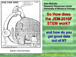
Alan Nicholls Research Resources Center University of Illinois at Chicago. So How does the JEM-2010F STEM work?. and how do you get good data out of it?. Optimizing STEM performance Specimen considerations JEM-2010F STEM optics & aberrations STEM Detectors

E N D
Alan Nicholls Research Resources Center University of Illinois at Chicago So How does the JEM-2010F STEM work? and how do you get good data out of it? UIC Electron Microscopy Service
Optimizing STEM performance • Specimen considerations • JEM-2010F STEM optics & aberrations • STEM Detectors • STEM (solid state & PMT); CCD (TEM imaging & EELS); EDX • FasTEM and STEM UIC Electron Microscopy Service
Specimen Considerations • Specimens for STEM need to be contamination free! • Do not touch any part that is used inside a vacuum system with your bare hands (I.e. Ion Mill holders etc) • IN PARTICULAR no part of the specimen holder, support or tools should ever be touched by ungloved hands. • Keep use of acetone down to a minimum - this is notoriously dirty and a primary source of hydrocarbon contamination. • Specimens that are glued will always need Plasma cleaning in the holder. 20 min Ar, 10 min O2 at 10W is recommended if the specimen is not damaged by oxygen. • Specimens can be plasma etched at 100W BUT must be in the Gatan duomill holder supplied NOT the specimen holder. Approximately 1nm/minute is removed. • DO NOT Plasma Clean any holder without a specimen in. • DO NOT EVER Plasma Clean heating or cooling holders! • Specimens on Carbon Films can be plasma cleaned or use an Infra Red Lamp with the specimen on a slide or filter paper at setting 6 for 30 minutes. UIC Electron Microscopy Service
STEM - the important parts UIC Electron Microscopy Service
Characteristics of different electron sources UIC Electron Microscopy Service
TEM>STEM Microscope should be aligned in TEM mode before entering STEM mode. If EELS spectra to be collected this should include GIF alignment. If you need to adjust A2 to optimize the probe this should be done before TEM alignment. A2 adjustments are only necessary for ultimate imaging resolution and should be done slowly! UIC Electron Microscopy Service
Nomenclature TEM STEM Gun N/A N/A Condenser Aperture Condenser Stigmator Objective Aperture Objective Stigmator (Virtual Objective Aperture) (Condenser Stigmator) Objective Aperture Objective Stigmator N/A N/A X Cond X Specimen Obj X UIC Electron Microscopy Service
NB Increasing Condenser lens strength increases the demagnification Decreasing A2 increases the demagnification :- the electrostatic focussing effect is the difference between A2 and A3 (voltage applied to each stage of accelerator (~55kV)) But increasing demagnification lowers beam current as defining aperture after condenser lenses UIC Electron Microscopy Service
STEM - How much demagnification do we need for atomic resolution? Source size ~170nm C1=6V; C2=4.7V; Demag 570 C1=7.07V; C2=4.64V; Demag 860 C1=8V; C2=4.61V; Demag 1185 OPTIMUM To get to 0.13nm use A2 to increase gun demagnification - reduce 7.3>6.8 Beam size at specimen 0.2nm Total demagnification ~850 UIC Electron Microscopy Service
TEM mode v STEM mode TEM - Image is readout in parallel from the whole illuminated area. All pixcels in the image are exposed at the same time. Specimen Detector STEM - Image is read out in serial from area scanned on the specimen. Intensity from each pixcel is read out and displayed independently in order. UIC Electron Microscopy Service
HADF EELS BF UIC Electron Microscopy Service
Effect of Cs on Ronchigram Increasing Objective lens strength UIC Electron Microscopy Service
Stigmating using the Ronchigram b a c Ronchigram from amorphous area. Select Scan mode Spot 1 and a magnification above 100Kx. a) underfocus astigmatic b) underfocus stigmated c) Gausian focus stigmated (almost!) Red circle marks unaberrated part of Ronchigram that should be selected by Objective aperture UIC Electron Microscopy Service
< Au contact layer on GaAs - 0.2nm probe, (C1 6.06; C2 4.65; A2 7.3) Si dumbells resolving 0.136nm 004 spacing with 0.13nm probe > (C1 6.06; C2 4.65, A2 6.8) UIC Electron Microscopy Service
JEOL HADF Detector UIC Electron Microscopy Service
Photomultiplier Tube Radiation causes photoelectrons to be generated by cathode. These are multiplied by the dynode chain (typically 8 elements) giving a 108 amplification of the signal. UIC Electron Microscopy Service
So which STEM detector is better? Solid state or PMT based • Easy to fabricate • Cheap to replace • Can be cut into any shape • Gain of system is high with a DQE of 0.9 • Noise level is low • Good at TV rate or low signal • BUT • Large dark current • DQE poor for low intensity • Electron beam damage • Insensitive to low energy electrons • BUT • scintillator not as robust as SSD • more expensive and bulky For Z contrast STEM PMT is best! UIC Electron Microscopy Service
Gatan Imaging Filter UIC Electron Microscopy Service
CCD detector components UIC Electron Microscopy Service
CCD Readout Read out rates can be as fast as 0.01s per frame. CCD can be re-exposed once read out. Repeat until all rows are read out CCD arrays have:- low noise and good DQE when cooled. High dynamic range BUT they are expensive ($250K for 4Kx4K CCD) UIC Electron Microscopy Service
EELS Spectrum from Graphitic Carbon In STEM mode, with 0.2nm, probe use 0.1s for zero loss region and, as a starting point, 1s per 100eV to look at higher losses (eg O at 532eV - 5sec) UIC Electron Microscopy Service
XEDS Spectrum from BSCCO Typically need a > 0.25nA to collect a statistically significant spectrum in 100sec (I.e. 0.5-1nm spot size 50-70mm CA). Can collect spectra with 0.2nm probe for ID of Major (>10%) components. UIC Electron Microscopy Service
Spectrum Imaging EELS only XEDS & EELS UIC Electron Microscopy Service
XEDS Spectrum Imaging • Acquire spectrum at each point in image typically using 1nm probe to get sufficient X-ray signal. • Short acquisition time at each point and multiple scans. 128x128 SI usually takes 30-45 minutes to get significant data • Data can be interrogated afterwards to generate spectra, new maps and linescans UIC Electron Microscopy Service
XEDS Spectrum Imaging LINESCAN example. For planar defects data can be, post acquisition, integrated parallel to the interface UIC Electron Microscopy Service
FasTEM Start Up • Programs must be started in the order listed. • FasTem Server and GIF are usually left running • You MUST Login to FasTem server before opening the Client (Control window). • FasTem Video Server does not need to be running. UIC Electron Microscopy Service
Multi Function WOB/DEF/STIG MAG/DIFF Select TEM Image Shift Y TEM Image Shift X Simple Knobset Q.Beam Selector Image Save Detector Select Brightness Focus UIC Electron Microscopy Service
FasTEM GUI UIC Electron Microscopy Service
FasTEM Client Selector • Projector alignment settings are stored for the different detectors. Please make sure that you center the illumination in probe size 1-3 at 100Kx • CAM TOP is not used • MSC is not used (used for above GIF CCD camera for TEM) • CAM BOT is the off axis camera (or other TV rate camera) • SCRN is the fluorescent screen • STEM is for Scanning mode • GIF is for the Gatan Imaging Filter (EELS & Filtered TEM imaging) UIC Electron Microscopy Service
FasTEM Client STEM Selector Mode EM - TEM; AL - Alignment - center caustic figure with Condenser Def then illumination with Condenser Shift SM - STEM monitor; DM - STEM Digital Micrograph Active Detector TEI - JEOL HADF Detector EXT - Gatan STEM detector Scan Mode PIC/RDC - Full Frame/ Reduced Frame SPOT/SPOT1/SPOT2 - Spot modes, Spot1 should be used for Ronchigram UIC Electron Microscopy Service
FasTEM Client STEM Selector Probe Size & Camera Length -choose from dropdown list. NB Spot size on ASID unit affects probe size selected through FasTEM - Make sure Small is selected. Alignment Function Default is “Projector” for centering beam on detector. Change to “Condenser 2 (Beam Tilt)” for electronic specimen shift - be careful miss-aligning column! UIC Electron Microscopy Service
STEM set up • Choose appropriate probe size • Choose appropriate camera length UIC Electron Microscopy Service
Digital Micrograph main window UIC Electron Microscopy Service
Digiscan STEM controls • Scan Setup • Select - 256, 512 and 1024 are set up for phase locked imaging. Use Default for fast scanning (Pixcel time can be altered) • Waveform Monitor - Allows brightness and contrast to be optimized. • Control Beam - Beam position tool only visible when not scanning image. • NB Esc key stops scan immediately, Stop button only at the end of a frame. Record only acquires one frame UIC Electron Microscopy Service
Z-contrast STEM - summary • Align microscope in TEM mode at desired A2 (inc. GIF for EELS) • Enter STEM mode with largest CA (150mm). Go to Spot1 with magnification greater than 100Kx - choose spot size and appropriate camera length for Ronchigram (NB 1nm up may be too bright for camera - for large probe sizes put aperture in, wobble Objective lens and minimize wobble using X&Y aperture controls) • Correct for Astigmatism (preferably on amorphous region) move to area for imaging. If fringes are visible in Ronchigram put appropriate aperture on axis. If fringes are not visible specimen is too thick, too far of axis or has too thick amorphous surface layer - choose another area. • Choose appropriate camera length for STEM detector - insert detector change back to PIC mode. • Increase magnification to x4M and focus to get atomic resolution image! UIC Electron Microscopy Service