ARP Bolt Fatigue
This document explores the fatigue characteristics of ARP connecting rod bolts, highlighting the differences between fatigue crack surfaces and final fracture surfaces. It examines the initiation of cracks from the bolt's interior and their propagation towards the surface, showcasing microvoid coalescence due to interfacial cracking. An S-N diagram is presented to relate component life to stress levels, along with examples of cyclic fatigue failure indicated by beach marks. The text emphasizes the design strength and endurance of ARP bolts in performance applications.

ARP Bolt Fatigue
E N D
Presentation Transcript
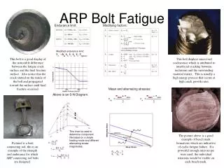
Endurance limit: Modifying factors: ARP Bolt Fatigue Modified endurance limit: This bolt is a good display of the noticeable difference between the fatigue crack surface and the final fracture surface. Also notice that the crack started on the inside of the bolt and propagated toward the surface until final fracture occurred. This bolt displays microvoid coalescence which is attributed to interfacial cracking between inclusions and the surrounding material matrix. This is usually a high energy process that occurs at high crack growth rates. Mean and alternating stresses: Above is an S-N Diagram. This chart is used to determine component life based on a single loading mode and different alternating stress magnitudes. The picture above is a good example of beach mark formations which are indicative of cyclic fatigue failure. If a powerful enough microscope were used, the individual striations would be visible on each beach mark. Pictured is a bent connecting rod, this is an example of the strength and endurance for which ARP connecting rod bolts are designed.