Parallel Port Interfacing Part 1: General Digital Data Communication
Learn about parallel and serial communication in digital data transmission, identification of parallel ports on IBM PC, pin configurations, accessing parallel port in software, addressing different types of addresses in C language, logic levels, and practical control of devices through parallel port interfacing.

Parallel Port Interfacing Part 1: General Digital Data Communication
E N D
Presentation Transcript
PARALLEL PORTINTERFACINGPART#1 By MUEEN SAJJAD
General Types of Digital Data Communication • Parallel • Serial Parallel Parallel communication requires as much wires as the no. of bits in a word for its transmission. Word may be a combination of 4,8,16,32 or 64 bits etc. Serial serial communication usually requires a minimum of 2 wires for data transmission in one direction. One wire is for data and other is for ground.
Parallel port identification on IBM PC • Usually ports are found on the rear of computer and are of the following two types; • Male ports having pins coming out of port. 2) Female ports having holes for pins. • Parallel port is generally a 25 pin female connector with which a printer is usually attached.
i. Data port ii. Status port iii. Control port Data port: It includes pin 2 to pin 9 with pin names Data-0 to Data- 9 It is usually for data output according to old “standard parallel port” standard. Address Bit no. Pin Name Pin Number Base +0 (e.g. 0×378) 7 Data 7 Pin 9 6 Data 6 Pin 8 5 Data 5 Pin 7 4 Data 4 Pin 6 3 Data 3 Pin 5 2 Data 2 Pin 4 1 Data 1 Pin 3 0 Data 0 Pin 2 Grouping Of Parallel Port Pins
Address Bit no. Pin Name Pin Number Base +1 (eg 0×379) 7 Busy Pin 11 (hardware inverted) 6 Ack Pin 10 5 Paper Out Pin 12 4 Select Pin 13 3 Error Pin 15 2 Irq - 1 Reserved - 0 Reserved - ii. Status Port Status port is an input only port i.e. Data can’t be output on this port but it can only be read.
Address Bit no. Pin Name Pin Number Base +2 (eg 0×37A or 37AH) 7 Unused - 6 Unused - 5 Enable bi-directional - 4 EnableIrq Via Ack-line - 3 Select printer Pin 17 (Hardware Inverted) 2 Initialize printer Pin 16 1 Auto line feed Pin 14 (Hardware Inverted) 0 strobe Pin 1 (Hardware Inverted) iii. Control port Control port is a read / write port. For printer purposes it is write only port.
How to access parallel port pins in the software. • Parallel port is assigned a unique I/O address which is generally among the following: • i) 378h (mostly the case) • ii) 278h (normally found when there are more than one parallel ports) • iii)3BCh (Rare case) • How to know the port address on your pc • Restart your computer go into BIOS. Then see the address of the port there. • If it is set auto hen there are two options: • i) Explicitly assign an address in the BIOS. • ii) Check the address in Windows by going to • Control panel System Device Manager PortsPrinter portProperties Resources Input/Output Range.
Difference between memory address space and I/O address space • In Intel family of x86 processors the memory addresses and I/O addresses are separate • Memory addresses • They depend upon the RAM/ROM present in your PC & Address lines. • I/O • This address space is dependent upon no. of address lines available for accessing I/O devices. • How to address above two type of addresses in C Language • Memory addresses are ,generally, not known to a C programmer the programmer can refer to an address by using pointer notation. • I/O addresses are accessed in Turbo C/C++ environment by using following Library functions • i) Inport • ii) Inportb • iii) Outport • iv) Outportb
Relation between bits present at the port address and voltage levels on port pins. • Each bit present at base address of the port has direct link with the voltage level on corresponding port pin. • i.e. a ‘1’ in register at I/O address corresponds to logic high at port pin. • A brief overview of logic high and logic Low levels of parallel port. • In parallel port • · Logic high means a voltage of +5V w.r.t ground. • · Logic low means a voltage of 0V w.r.t ground. • Deviation from above ‘bit-logic level’ relation • In case of hardware-inverted pins the above described relation of bit and logic level is reversed i.e. ‘1’ corresponds to 0V on port pin. Examples are busy and strobe.
Demonstration of control of light Bulb through parallel port Schematics of circuit
The Software Controlling part #include<stdio.h> void main(void) { outportb(0x378,0x01); //turn on the bulb getch(); //wait for any key to be pressed outportb(0x378,0x00); //turn off the bulb getch(); // wait for a key to be Pressed } C program to control ON/OFF Through keyboard for (int i=1; i<=5,i++); { outport b (0x378,0x01); //turn on the bulb delay (1000); // wait for 1000msec=1sec outportb(0x378,0x00); //turn off the bulb } C program to have the bulb blink for five times
Range of voltage for logic high and logic low Above circuit might have been connected as shown below • But it will give you incorrect results. The reason is the range of voltage levels that are considered high or low. • Parallel port is TTL(transistor transistor logic) compatible in which • Logic high is a voltage between 0 to 0.8 V • Logic low is a voltage between 2.0 to 5V • Any voltage in between the above rage is undefined. • A voltage higher than the logic high or lower than the logic low can damage your port or any other TTL circuit.
Some considerations of control port Control port can be used both for input or out put. However there are some deviations Open Collector Output In some hard wares control port pins are open collector. Its equivalent circuit is as follows: Logic States of Open Collector Pin i) Logic low (0V). It is actually a short circuit to ground as transistor is conducting. ii)Logical high ( Open Circuit)
How to set a Logic High Voltage level on Open Collector • You should connect an external resistor with pin to get logic high voltage which depends upon the supply voltage you use. • In case of parallel port don’t use Vcc greater than +5V.
Introduction to buffering for parallel interfacing • Buffers are normally used for purpose of load isolation. • For digital interfacing we use digital buffers or inverters likeCD4050 (buffer) CD4049 (inverter)OR 74 LS245 74 LS244 TTL • Why we need Buffer? Introduction to Source & Sink Currents • Source current • In high output level the port pin or any TTL circuit can provide a certain maximum amount of output current while maintaining logic high level. This current is called source current. • For parallel port this may be up to a minimum of 1mA among various ratings. • Beyond this current, your voltage level decreases. This must be avoided.
Sink current • In case of a pin being in logic low state there is a minimum amount of current that the pin can absorb called sink current. • A current larger than sink current can result in severe damage to the logic device. • The amount of the sink current is usually higher than corresponding source current for the same device. • The usual range is about 10mA for parallel port. • Advantage of buffers • Buffers have better ratings of the source and sink currents. • They provide protection to your costly circuits in the event a pin is over loaded by excessive source/sink Current or an over voltage applied. • It is always a good practice to use buffers for your costly logic devices for both data in and out.
Software Code for output of numbers //program for the out put of the binary no.’s from 0 to 255) void main (void) { for (int i=0;i<256;i++) { outportb(0x378,i) delay(100); } } Software code to implement Moving Light char k=1; int i; for(i=0; i<8; i++) { outportb(0x378, k<<i); delay(500); } k=128; for(i=0; i<8; i++){ outportb(0x378, k>>i); delay(500); }
PARALLEL PORTINTERFACINGPART#2 ADVANCED TECHNIQUES IN PARALLEL PORT INTERFACING
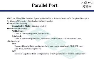
SPP standard parallel port not bi-directional Bi-directional standard parallel port with bi-directional facility EPP Enhanced Parallel port ECP Extended Capabilities parallel port Introduction to Bi-directional Parallel Port • These days starting from PC’s equipped with Pentium processors, the parallel ports have Bi-directional read/write facility. • Bi-directional means that you can read byte (8 bits) from parallel port which traditionally was an output only port in the old PC’s. • In order to check whether your port is configured for it, restart your PC and go into BIOS see the portion related to the parts. You will find port address as well as its type, usually the options are as follows
How to configure for Bi-directional Facility? To accomplish data in through data port you should: 1. set your port to bi-directional, EPP or ECP. 2. write a 1 in bit 5 of control port by using following commands Example Code: x = inportb(0x37A); //read control port byte y = x | 0x20; //perform a bit-wise OR with //1 in position5 to set bit 5 of x 1 //and store the result in y as 0x20 = 00100000 outportb(0x37A,y); //send byte to control port Now you can give any external 8-bit digital input on data pins (pin2 to pin 9) and read the data by using z=inportb(0x378);
Introduction to EPP and ECP Before we go into details of the EPP & ECP let us see why it was designed. Printer Hand shake used in standard parallel port (Centronics Standard) According to this standard , following hand shake was used: All above signaling, was done by software in which PC had to wait for a response from printer before outputting the next signal. It was a slow process with data rate of 50KB/sec to 150KB/sec.
Introduction to EPP (Enhanced Parallel Port) handshake EPP was designed to do, the above described, handshaking by a separate hardware chip instead of main processor. It is described as follows: EPP Data Write Cycle: The only port to be done in software is to write the Byte to be sent at Data port (EPP) whose address is (base address+4) {eg.0x37C} Note: this data port is different from the data port of SPP. However you can still use that data port of SPP by usual way. All above signals are generated automatically in hardware.
Description of handshake given on Last slide i) I) The software programs writes the byte to be sent at EPP data register (Base +4) ii) Write is placed low by PC to indicate the printer that some data is to be sent. iii) After placing the Write low, data is placed on data lines (pin 2 to pin 9) iv) Wait pin is checked. It is an input from the printer. If it is low then it means that printer is waiting for receiving data from PC. This being the case, the PC pulls DATA STROBE low to indicate the printer that it should read data from data line. v) The printer reads data from Data lines and brings the WAIT line high fir a short duration. This indicates to the PC that printer has received data, so it is Ok to end EPP data write cycle. vi) DATA STROBE is brought high. WRITE is also brought high. vii) EPP write cycle Ends here.
Description of Handshake used for EPP Address Read Cycle. a. The printer informs the PC that it has to send some data to PC by sending signal on interrupt line (pin 10, ACK in SPP). This Depends upon software. Any other input line may be used as well for this signaling. b. Whenever pc is free, it responds to this signal and reads EPP address register (Base+3). c. ADDR STROBE is pulled low if Wait is low. This is done automatically when processor reads the Address Register. This signals informs the printer that host (PC) is ready to start an EPP read cycle. d. Host waits for acknowledgement from Printer by waiting for WAIT line going high. e. As Wait line goes high, data is read from data liens (pin 2 to 9) f. Addr Strobe is pulled high. This ends EPP read cycle.
Time-out indication in EPP There is a possibility that host (PC) starts a write cycle but never receives acknowledgement from printer when no printer is attatched. As this operation is done in hardware so the PC will continue waiting & your computer will halt. In order to avoid this a Watchdog timer scheme is used it is described as follows. i) When host writes data to address/Data port of the EPP, a timer is started at the same time. ii) Now host waits for an acknowledgement on WAIT line becoming high. If it does not happen within about 10μsec, (depending on port), then a time out is indicated by setting Bit0 of status port (base+1). iii) The host stops waiting and informs the user about the problem.
How to setup port for Programming using EPP features Before you can start any EPP cycle by reading/writing to EPP data and address port, the port must be configured correctly. In idle state, an EPP port should have its Address Strobe, Data strobe, wait and reset lines high. So it is better to initiate these lines manually by writing xxxx0100 to control port(base+2). For details please consult the document “Interfacing The Enhanced Parallel Port” found in Pdf form on “www.beyondlogic.org”. Here you will find most of the details about interfacing SPP, EPP and ECP with software example as well.
A brief introduction to ECP (Extended Capability Port) Enhancements in ECP ECP supports SPP and EPP features. In addition it has following enhancements. i) It can use DMA (direct memory access) feature in order to transfer a block of data from memory automatically without the use of CPU. ii) It can use (first in first out) FIFO buffers to transfer more than one byte automatically before the attention of CPU is required. iii) It supports data compression by using RLE (Run Length Encoding) scheme. This scheme helps to transmit a single byte if a long string of this same byte is required to be transmitted. iv) It supports a method of channel addressing by which you can communicate with different modules of the target. For example with Fax, copier and printer in a single machine containing these 3. For details about ECP and its programming details please consult the document: “Interfacing The Enhanced Parallel Port” found in pdf form on ‘www.beyondlogic.org”. Here you will find most of the details about interfacing SPP, EPP and ECP with software example as well.