Download
1 / 86
920 likes | 1.51k Vues
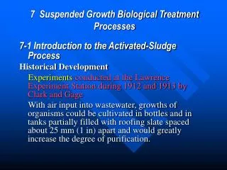
7 Suspended Growth Biological Treatment Processes. 7-1 Introduction to the Activated-Sludge Process Historical Development Experiments conducted at the Lawrence Experiment Station during 1912 and 1913 by Clark and Gage

E N D
7 Suspended Growth Biological Treatment Processes 7-1 Introduction to the Activated-Sludge Process Historical Development Experiments conducted at the Lawrence Experiment Station during 1912 and 1913 by Clark and Gage With air input into wastewater, growths of organisms could be cultivated in bottles and in tanks partially filled with roofing slate spaced about 25 mm (1 in) apart and would greatly increase the degree of purification.
Lockett found that the sludge played an important part. The basic activated-sludge treatment process, as illustrated on Fig. 7-la and b, consists of the following three basic components: (1) a reactor in which the microorganisms responsible for treatment are kept in suspension and aerated; (2) liquid-solids separation, usually in a sedimentation tank; and (3) a recycle system for returning solids removed from the liquid-solids separation unit back to the reactor.
An important feature of the activated-sludge process is the formation of flocculent settleable solids . For these applications, various modifications of conventional activated-sludge processes are used, including sequencing batch reactors, oxidation ditch systems, aerated lagoons, or stabilization ponds.
Evolution of the Activated-Sludge Process A number of activated-sludge processes and design configurations have evolved since its early conception as a result of (1) engineering innovation in response to the need for higher-quality effluents from wastewater treatment plants; (2) technological advances in equipment, electronics, and process control; (3) increased understanding of microbial processes and fundamentals; and (4) the continual need to reduce capital and operating costs.
The use of a plug-flow process became problematic when industrial wastes were introduced because of the toxic effects of some of the discharges. With the development of simple inexpensive program logic controllers (PLCs) and the availability of level sensors and automatically operated valves, the sequencing batch reactor (SBR) process (see Fig. 7-1c) became more widely used by the late 1970s, especially for smaller communities . Some of the stages are not aerated (anaerobic or anoxic stages) and internal recycle flows may be used.
Recent Process Developments As noted above, numerous modifications of the activated-sludge process have evolved in the last 10 to 20 years, aimed principally at effective and efficient removal of nitrogen and phosphorus.
7-2 Wastewater Characterization Activated-sludge process design requires determining (1) the aeration basin volume, (2) the amount of sludge production, (3) the amount of oxygen needed, and (4) the effluent concentration of important parameters.
7-3 Fundamentals of Process Analysis and Control Selection of Reactor Type Important factors that must be considered in the selection of reactor types for the activated-sludge process include (1) the effects of reaction kinetics, (2) oxygen transfer requirements, (3) nature of the wastewater, (4) local environmental conditions, (5) presence of toxic or inhibitory substances in the influent wastewater, (6) costs, and (7) expansion to meet future treatment needs.
Selection of Solids Retention Time and Loading Criteria The common parameters used are the solids retention time (SRT), the food to biomass (F/M) ratio (also known as food to microorganism ratio), and the volumetric organic loading rate(Lv). Solids Retention Time The SRT, in effect, represents the average period of time during which the sludge has remained in the system. SRT is the most critical parameter for activated-sludge design as SRT affects the treatment process performance, aeration tank volume, sludge production, and oxygen requirements.
Sludge Production Sludge will accumulate in the activated-sludge process if it cannot be processed fast enough by an undersized sludge-handling facility. The observed yield decreases as the SRT is increased due to biomass loss by more endogenous respiration. The yield is higher when no primary treatment is used, as more nbVSS remains in the influent wastewater(A-B).
Oxygen Requirements As an approximation, for BOD removal only, the oxygen requirement will vary from 0.90 to 1.3 kg O2/kg BOD removed for SRTs of 5 to 20 d . Nutrient Requirements Using the formula C5H7NO2, for the composition of cell biomass, about 12.4 percent by weight of nitrogen will be required. The phosphorus requirement is usually assumed to be about one-fifth of the nitrogen value. As a general role, for SRT values greater than 7 d, about 5 g nitrogen and 1 g phosphorus will be required per 100 g of BOD to provide an excess of nutrients.
Other Chemical Requirements The amount of alkalinity required for nitrification, taking into account cell growth, is about 7.07 g CaCO3/g NH4-N. In addition to the alkalinity required for nitrification, additional alkalinity must be available to maintain the pH in the range from 6.8 to 7.4. Typically the amount of residual alkalinity required to maintain pH near a neutral point (i.e., pH ≈ 7) is between 70 and 80 mg/L as CaCO3.
Mixed-Liquor Settling Characteristics Clarifier design must provide adequate clarification of the effluent and solids thickening for the activated-sludge solids. Two commonly used measures developed to quantify the settling characteristics of activated sludge are the sludge volume index (SVI) and the zone settling rate . The SVI is determined by placing a mixed-liquor sample in a 1- to 2-L cylinder and measuring the settled volume after 30 min and the corresponding sample MLSS concentration. For example, a mixed-liquor sample with a 3000 mg/L TSS concentration that settles to a volume of 300 mL in 30 min in a 1-L cylinder would have an SVI of 100 mL/g. A value of 100 mL/g is considered a good settling sludge (SVI values below 100 are desired). SVI values above 150 are typically associated with filamentous growth.
Use of Selectors Because solids separation is one of the most important aspects of biological wastewater treatment, a biological selector (a small contact tank) is often incorporated in the design to limit the growth of organisms that do not settle well. An appropriate selector design can be added before the activated-sludge aeration basin.
Process Control To maintain high levels of treatment performance The principal approaches to process control are (1) maintaining dissolved oxygen levels in the aeration tanks, (2) regulating the amount of return activated sludge (RAS), and (3) controlling the waste-activated sludge (WAS). The parameter used most commonly for controlling the activated-sludge process is SRT.
Dissolved Oxygen Control. When oxygen limits the growth of microorganisms, filamentous organisms may predominate and the settleability and quality of the activated sludge may be poor. In general, the dissolved oxygen concentration in the aeration tank should be maintained at about 1.5 to 2 mg/L in all areas of the aeration tank.
Return Activated-Sludge Control Return sludge concentrations from secondary clarifiers range typically from 4000 to 12,000 mg/L . Settleability If the settleable solids occupied a volume of 275 mL after 30 min of settling, the percentage volume would be equal to 38 percent [(275 mL / 725 mL) * 100]. If the plant flow were 2 m3/s, the return sludge rate should be 0.38 × 2 m3/s = 0.76 m3/s.
Sludge Blanket Level The optimum level is determined by experience and is a balance between settling depth and sludge storage. The optimum depth of the sludge blanket usually ranges between 0.3 and 0.9 m. Considerations: (1) diurnal flow variations (2) sludge production variations (3)changes in the settling characteristics of the sludge.
Sludge Wasting An alternative method of wasting sometimes used is withdrawing mixed liquor directly from the aeration tank or the aeration tank effluent pipe . Oxygen Uptake Rates OUR or respiration rate used to assess the presence of toxic or inhibitory substances in the influent wastewater.
Microscopic Observations Specific information gathered includes • changes in floc size and density • status of filamentous organism growth in the floc • presence of Nocardia bacteria, • type and abundance of higher life-forms such as protozoans and rotifers. A decrease in the protozoan population may be indicative of DO limitations, operation at a lower SRT inhibitory substances in the wastewater.
Operational Problems The most common problems encountered in the operation of an activated-sludge plant are bulking sludge, rising sludge, and Nocardia foam. Bulking Sludge In a bulking sludge condition, the MLSS floc does not compact or settle well, and floc particles are discharged in the clarifier effluent.
The other type of bulking, viscous bulking, is caused by an excessive amount of extracellular biopolymer .Viscous bulking is usually found with nutrient-limited systems or in a very high loading condition with wastewater having a high amount of rbCOD.
This structure, in contrast to the preferred dense floc with good settling properties, has an increased surface area to mass ratio, which results in poor settling. The classification system is based on morphology (size and shape of cells, length and shape of filaments), staining responses, and cell inclusions.
One of the kinetic features of filamentous organisms that relates to these conditions is that they are very competitive at low substrate concentrations whether it be organic substrates, DO, or nutrients. Thus, lightly loaded complete-mix activated-sludge systems or low DO (<0.5 mg/L) operating conditions provide an environment more favorable to filamentous bacteria than to the desired floc-forming bacteria.
When the influent wastewater contains fermentation products such as volatile fatty acids(VFA) and reduced sulfur compounds (sulfides and thiosulfate), Thiothrix can proliferate. View the mixed liquor under the microscope. A reasonable quality phase-contrast microscope with magnification up to 1000 times (oil immersion) is necessary to view the filamentous bacteria or fungi structure and size.
Process Loading/Reactor Configuration In many cases, complete-mix systems with long SRTs and subsequent low F/M ratios experience filamentous growths. In such systems, the filamentous organisms are more competitive for substrate. We can use selector processes to solve these problems because they provide conditions that cause selection of floc-forming bacteria in lieu of filamentous organisms as the dominant population.
Temporary Control Measures In an emergency situation or while the aforementioned factors are being investigated, chlorine and hydrogen peroxide may be used to provide temporary help. Chlorination of return sludge has been practiced quite extensively as a means of controlling bulking. Rising Sludge The most common cause of this phenomenon is denitrification, in which nitrites and nitrates in the wastewater are converted to nitrogen gas. If enough gas is formed, the sludge mass becomes buoyant and rises or floats to the surface.
Nocardia Foam. Two bacteria genera, Nocardia and Microthrix parvicella, are associated with extensive foaming in activated-sludge processes. These organisms have hydrophobic cell surfaces and attach to air bubbles, where they stabilize the bubbles to cause foam.
Nocardia has a filamentous structure, and the filaments are very short and are contained within the floc particles.Microthrix parvicella has thin filaments extending from the floc particles. The foam is thick, has a brown color, and can build up in thickness of 0.5 to 1 m, but is more pronounced with diffused aeration and with higher air flowrates.
Methods that can be used to control Nocardia include (1) avoiding trapping foam in the secondary treatment process, (2) avoiding the recycle of skimmings into the secondary treatment process, and (3) using chlorine spray on the surface of the Nocardia foam. The addition of a small concentration of cationic polymer has been used with some success for controlling Nocardia foaming .Reducing the oil and grease content from discharges to the collection system from restaurants, truck stops, and meatpacking facilities by effective degreasing processes can help control potential Nocardia problems.
Activated-Sludge Selector Processes The high substrate concentration in the selector favors the growth of nonfilamentous organisms. A selector is a small tank (20 to 60 min contact time) or a series of tanks in which the incoming wastewater is mixed with return sludge under aerobic, anoxic, and anaerobic conditions. The goal in the selector is to have most of the rbCOD consumed by the floc-forming bacteria.
With biological nutrient-removal processes(脱氮除磷), improved sludge-settling characteristics, and, in many cases, minimal filamentous bacteria growth has been observed. The anoxic or anaerobic metabolic conditions used in these processes favor growth of the floc-forming bacteria.The filamentous bacteria cannot use nitrate or nitrite for an electron acceptor.
For continuous-flow applications, at least two SBR tanks must be provided so that one tank receives flow while the other completes its treatment cycle.
Sludge Wasting in SBRs A unique feature of the SBR system is that there is no need for a return activated-sludge (RAS) system. Because of the substrate concentration changes with time, the substrate utilization and oxygen demand rates change, progressing from high to low levels.
7-5 Process for Biological Nitrogen Removal Nitrogen removal is needed to prevent eutrophication), or for groundwater recharge or other reuse applications. Nitrogen removal can be either an integral part of the biological treatment system or an add-on process to an existing treatment plant. Following the discussion of design issues, design examples are provided for (1) the anoxic/aerobic process, (2) step-feed anoxic/aerobic process, (3) intermittent aeration, (4) a sequencing batch reactor, and (5) postanoxic denitrification with methanol addition.
First, regions of low DO or zero DO concentration may be present within the basin as a function of the mixing regime. Second, activated-sludge floc can contain both aerobic and anoxic zones.
Single-Sludge Simultaneous Nitrification Denitrificatlon (SNdN) Processes The nitrification and denitrification rates are a function of the reaction kinetics, floc size, floc density, floc structure, rbCOD loading, and bulk liquid DO concentration.
Fig. 7-16 Operation of a Nitrox oxidation ditch process using intermittent aeration: (a)aerobic conditions; (b)anoxic conditions; (c)variations in ORP,DO,ammonia and nitrate
7-6 Processes for Biological Phosphorus Removal Barnard (1974) was the first to clarify the need for anaerobic contacting between activated sludge and influent wastewater before aerobic degradation to accomplish biological phosphorus removal. Biological Phosphorus-Removal Processes The main difference between the Phoredox (A/O) process and the A2O processes shown on Fig. 7-17a and b is that nitrification does not occur in the Phoredox (A/O) process. Low operating SRTs are used to prevent the initiation of nitrification.