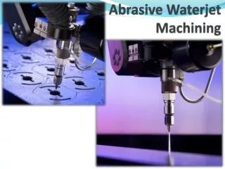
Abrasive Processes
Abrasive machining involves material removal by the action of hard abrasive particles that are usually in the form of a bonded wheel.

Abrasive Processes
E N D
Presentation Transcript
Abrasive machining involves material removal by the action of hard abrasive particles that are usually in the form of a bonded wheel. These operations are generally used as finishing operations, although in some cases they are used for high metal removing rates rivaling of conventional machining operations. These processes include grinding, honing, lapping, super finishing, polishing and buffing. Abrasive Processes
The reasons for the commercial and technological importance of the abrasive processes are; • They can be used on all types of materials, ranging from soft to hard materials. • Some of theses processes can produce extremely fine surface finish. (see the previous table). • The dimension of the product can be held to extremely close tolerances.
Grinding it is a material removal processes in which the abrasive particles are contained in a bonded grinding wheel that operates at very high surface speeds. The grinding operation is much like the milling operations. Cutting occurs either the periphery or the face of the grinding wheel, similar to the peripheral milling and face milling. The peripheral grinding is much common than the face one. Grinding wheel Grinding wheel
The difference between the milling operations and the grinding operations are;
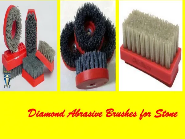
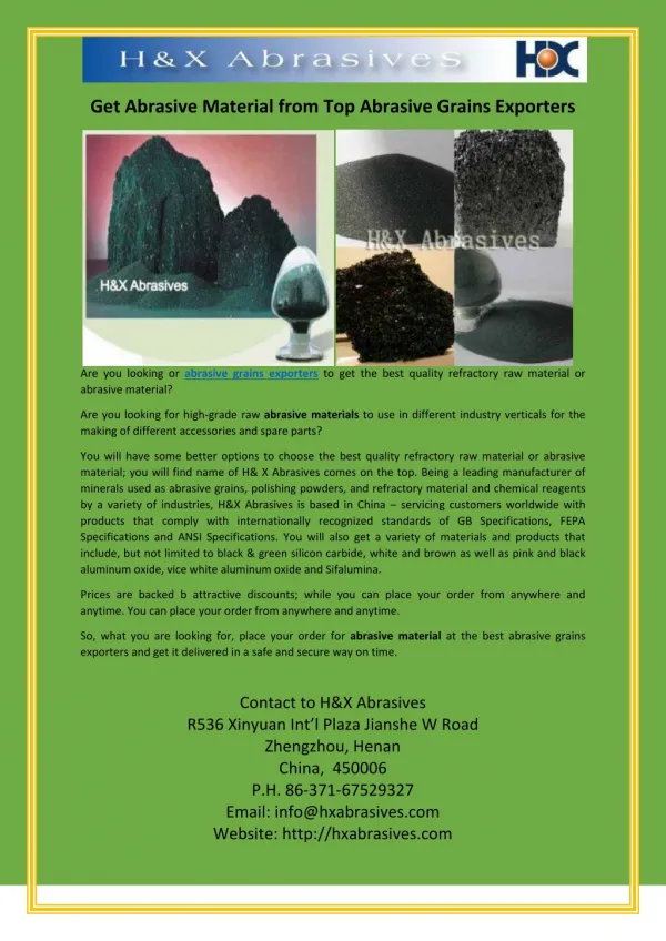
Grinding wheel The grinding wheel is the tool with which the grinding action is performed. It consists of abrasive particles and bonding materials, (as shown in the Fig.). • The bonding material holds the particles in place and build the shape and structure of the wheel. • These two components and the way they are fabricated determine the parameters of the grinding wheel; • Abrasive materials. 2. Grain size • 3. Bonding materials. 4. Wheel grade • 5. Wheel structure
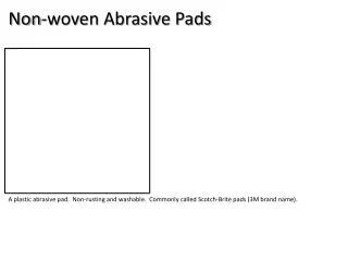
1- Abrasive materials • Generalproperties of abrasive materials are; • High hardness • Wear resistance • Toughness • Friability; it is the ability of the abrasive material to fracture, when the cutting of the grain becomes dull, thereby exposing a new cutting edge (sharp cutting edge).
2- Grain size • It’s an important parameter in determining the surface finish and metal removing rate. • Grain size surface finish • Grain size material removal rate . • Harder work materials required smaller grain size while the softer materials required larger grit size. Grit size is measured using a screen mesh. Smaller grit size has larger numbers. • The selection of the grit size must take into consideration the above 3 points.
3- Bonding materials • The bonding material holds the particles in place and build the shape and structure of the wheel. • The desirable properties of bonding materials are; • Strength (withstand centrifugal forces). • Toughness (resist shattering in shock loads). • Hardness. • Temperature resistance (withstand high temperature). • Hold abrasive material in place rigidly to accomplish the cutting forces while allowing the grain that are worn to be dislodged so that new grains can be exposed.
4- Wheel Structure Refers to the relative spacing of the abrasive grains in the wheel. It is measured on a scale ranges from open to dense (the ratio between the grains proportion to bond materials proportion). Open is used for chip clearance. Dense one is used for surface finish and dimensional control. Vg + Vb + Vp = 1.0 Vg grains proportion Vb bond materials proportion Vp voids (pores) proportion
Wheel Grade Indicates the wheel’s bond strength in retaining the abrasive grits during cutting. Dependent on the present of bonding materials (Vb). It is measured on a scale ranges from soft to hard. Soft one, lose the grains readily, is used for low materials removal rates and when machining hard work material. Hard one, retains the grains, is used for high materials removal rates and when machining soft work material.
Analysis of the grinding Process b (D) Vw w
There are two types of feed; Cross feed; motion of work table (w) In feed; the motion of the wheel into the work (d) - In the cutting, parameters and the grinding wheel parameters have a direct effect into; 1- Surface finish 2- Forces and energy 3- Temperature of the work surface 4- Wheel wear 5- Machining time.
Surface finish • It is affected by the size of the individual chips (note that small grit size get better surface finish). • Number of chips formed; • C is grits/mm2 (from 0.1 to 10) • That mean that the increase of V and C for a given wincrease the number of chips/time and improve the finish.
Forces and energy • U specific energy, Fc cutting force. • Specific energy in the grinding operations is much greater that in other conventional machining because; • The size effect in the machining. • High negative rake angle of the individual grains. • Not all the grits are engaged in actual cutting (cutting, plowing, and rubbing, Fig. 8.5). • Example 8.1 page 193
Temperatures at the work surface • The grinding process generates high temperature because the size effect and the high negative rake angle, this with high friction. • This high temperature can have several damaging effects; • Bums and cracks; • Bum is a discolorration on the surface • Cracks are perpendicular to the wheel speed direction • Softening of the work surface. • Residual stresses. • The proper application of the cutting fluids reduce friction and remove heat and washing away chips.
Wheel wear • In the grinding wheel there are three types of wear (Fig. 8.6); • Grain fracture, 1st region. • Attritions wear, 2nd region. • Bond fracture, 3rd region. • When the wheel in the 3rd region, it should be re-sharping (dressing operation) to; • Breaking off dulled grits. • Removing the chips. • Grinding ratio (GR) is between 95 to 125, depending on wheel speed which reduce the wear, while at too high speed both wear and temp. are increased and the grinding ratio is reduced with the surface finish.
Machining time B work width b grinding wheel width l work length Δ allowance (≈10mm) h total depth d infeed Vw the work speed w cross feed Example 8.2 page 199
Grinding operations • Used to finish products created with other operations. • Shapes to be grinded are plain surfaces, internal and external cylinders, and contour surfaces. • The contour surfaces, such as thread, are created by a special formed wheels, which are created in the tool rooms. • 1- Surface Grinding • Performed using either the periphery or the flat surface of the grinding wheel (face grinding). • The peripheral grinding is performed with a horizontal axis machines, while the face grinding is performed with a vertical axis machines, as shown in the figure.
Horizontal spindle with reciprocating worktable. Horizontal spindle with rotary worktable. vertical spindle with reciprocating worktable. Vertical spindle with rotary worktable. Note the direction of the cross feed and in-feed
2- cylindrical Grinding a- External cylindrical grinding the feed motions are either traverse feed (the wheel or workpiece or both) or plunge cut. b- Internal cylindrical grinding
3- Centerless Grinding • The workpiece is not held between center, then it used for high production rate machining, no holding time. • The regulating wheel rotates at lower speed and is inclined at a slight angle I, the feed rate of this wheel depending on its diameter, rotating speed, and its angle. External Centerless Grinding
The internal centerless grinding has two supporting rolls instead of the rest blade in the external one. Internal Centerless Grinding
d Feed 4- Creep Feed Grinding • In-Feed are 1000 to 10000 times greater then conventional one • Feed rates are reduced about the same proportion. • High MRR and productivity because of the continuous cutting. • Advantages; • High MRR • Improve accuracy • Reduced temperatures.
Related abrasive processes 1- Honing • To finish the bores of internal combustion engines, bearing, hydraulic cylinders, and gun barrels. • Performed with a set of bonded abrasive sticks. • Its motion is combination of rotation and linear motion. • Speed between 15 to 150 m/min. • Grit size between 30 and 600 Tool Operation
2- Lapping • Used to produce surface finish of extreme accuracy and smoothness. • Used in production of optical lenses, metallic bearing surface, and gages. • It used a fluid suspension of very small abrasive particles (in oils or kerosene) between the work and the lapping tool. • Common abrasives are aluminum oxide and silicon carbide with grit size between 300 and 600. • The tool takes the inverse shape of the work part. • Materials such as steel, CI, copper, lead and wood.
3- Superfinishing • Like honing but; • Shorter strokes • Higher frequancy, lower pressure • Lower workpiece speed. • Smaller grit size. • Only one stick is used
4- Polishing and Buffing • Polishing is used to remove scratches and burrs and smooth rough surfaces by means of abrasive grains attached to the polishing wheel rotating at high speed around 2250 m/min. • The wheel, flexible wheel, is made of leather, canvas, felt and papers. And grit size of 20 to 80 for rough, 90 to 120 for finish. • Buffing is similar to polishing with softer wheels, finer abrasive materials. • Speed ranging from 2400 to 5100 m/min.