USB Controlled Discharge Circuit for LED and HD44780 LCD using ATmega163
This project outlines the design of a USB-powered discharge circuit utilizing an ATmega163 microcontroller. It controls an LED indicator and an HD44780 LCD for displaying battery voltage and status during testing. The circuit includes a 3055 NPN FET and a 10-ohm, 10W resistor to manage battery discharge safely. The system is equipped with various digital outputs and analog inputs to monitor battery conditions and allow for efficient control over the charging and discharging processes. Enhance your electronics projects with this convenient and informative setup!

USB Controlled Discharge Circuit for LED and HD44780 LCD using ATmega163
E N D
Presentation Transcript
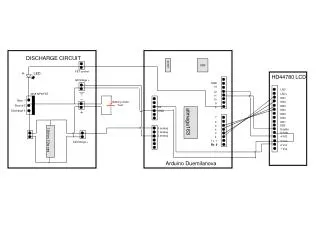
atmega163 DISCHARGE CIRCUIT USB power FET control LED HD44780 LCD fetVoltage + GND 13 LED- 12 3055 NPN FET LED+ 11 DB7 10 Gate 1 Battery Under Test DB6 9 Source 2 DB5 5V 8 DB4 Discharge 3 GND DB3 7 DB2 6 DB1 DB0 5 0 analog Enable 10ohm 10w res 4 1 analog 5 R/W 3 2 analog 4 R/S 2 3 Vee Tx 1 batVoltage + Rx 0 Rx 0 2 Vcc 1 Vss Arduino Duemilanova