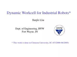
Dynamic Workcell for Industrial Robots
CLEMSON U N I V E R S I T Y. Dynamic Workcell for Industrial Robots. Dept. of Electrical and Computer Engineering Clemson University, SC. Yanfei Liu. Outline. Motivation for this research Current status of vision in industrial workcells

Dynamic Workcell for Industrial Robots
E N D
Presentation Transcript
CLEMSON U N I V E R S I T Y Dynamic Workcell for Industrial Robots Dept. of Electrical and Computer Engineering Clemson University, SC Yanfei Liu
Outline • Motivation for this research • Current status of vision in industrial workcells • A novel industrial workcell with continuous visual guidance • Work that has been done • Our prototype: camera network based industrial workcell • A new generic timing model for vision-based robotic systems • Dynamic intercept and manipulation of objects under semi-structured motion • Grasping research using a novel flexible pneumatic end-effector
Motivation for this research • Current industrial workcells • No vision or a single snapshot in certain locations • Disadvantages • Cannot deal with flexible parts • Cannot deal with uncertainty
Motivation for this research • Our novel dynamic workcell design • Manipulation is integrated with visual sensing • Applications ( reduce fixtures, handle objects on the ship)
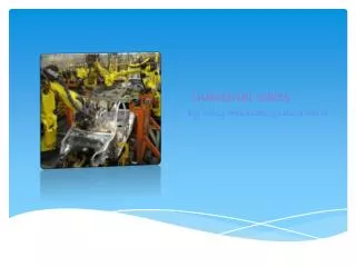
System architecture • A set of cameras embedded into the workcell • An industrial manipulator with its conventional controller
Experimental platform • Our prototype • Staubli RX130 manipulator with its conventional controller • Six cameras, wired to two PC-RGB framegrabbers mounted in a Compaq Proliant 8500 computer • V+ Operating systems and language • Alter command to accomplish real time motion
First part: A new generic timing model for vision-based robotic system
desired position e + power amplifiers control robot - camera Introduction • Classical visual servoing structure • eye-in-hand systems • Corke (1996), an eye-in-hand manipulator to fixate on a thrown ping-pong ball • Gangloff (2002), a 6-DOF manipulator to follow unknown but structured 3-D profiles. • part-in-hand systems • Stanvnitzky (2000), align a metal part with another fixed part • mobile robot systems • Kim (2000), a mobile robot system to play soccer
desired position e joint controller camera control robot encoders + - Introduction • Vision guided control structure • Allen (1993), a PUMA-560 tracking and grasping a moving model train which moved around a circular railway. • Nakai (1998), a robot system to play volleyball with human beings. • Miyazaki (2002), a robot accomplished a ping pong task based on virtual targets
Introduction • Three common problems in visual systems • Maximum possible rate for complex visual sensing and processing is much slower than the minimum required rate for mechanical control. • Complex visual processing introduces a significant lag (processing lag) between when reality is sensed and when the result from processing a measurement of the object state is available. • A lag (motion lag) is produced when the mechanical system takes time to complete the desired motion.
Previous work • the first two of the three problems have been addressed to some extent in previous works. All of these works neglect the motion time (motion lag) of the robot. • Corke and Kim, presented timing diagram to describe time delay, used discrete time models to model the systems and simplified these asynchronous systems to single-rate systems.
s2 s1 sensing u2 u1 image processing k q synchronizing tracking c1 … cN controlling finishing motion f processing lag motion lag Timing Model: notation
Timing Model: our prototype • Inherent values (obtained by analysis/measurement) • s = 33ms u = 19+30+14 = 63ms • wm = 39ms wf = (5+16+27)/3 = 16ms w = 39+16 = 55ms • l = s + u + w =151ms f = 130ms • User-variable values • c = 4ms q = 40ms
Experiments • Problem description • The most recently measured position and velocity of the object is where the object was (l+k) ms before, xt-l- k, vt-l- k • The current position, xt • N, d?
Experiments • Solutions Constraint:
Experiments: model validation • Setup • A small cylindrical object is dragged by a string tied to a belt moving at a constant velocity. • The robot will lunge and cover the object on the table with a modified end-effector, a small plastic bowl.
Experiments • Experiment description • We set q to two different values, 40 and 80, in these two sets of experiments. We let the object move at three different velocities. For each velocity, we ran the experiment ten times. • Results
Second part: Dynamic Intercept and Manipulation of Objects under Semi-Structured Motion
Scooping balls: problem description robot xt , yt : object position at time t vx , vy: object velocity at time t xr , yr: initial robot position xf , yf : final impact position x Unknown variables: yf , i y Closed loop Open loop Start tracking Make prediction (t) Impact (t+i)
Scooping balls: solution • Solutions • Object unsensed time • Time between the last instant when reality is sensed and the final impact time • Delay between visual sensing and manipulation
… … c1 c1 cN cN Timeline description: object unsensed time t processing lag(l) + k synchronizing tracking q q … controlling m 20 motion lag (f) finishing motion closed loop open loop t = l + k + 4m+ f m < N = 10, k < 30 + 14 = 44ms t = 151 + ( 40 + 44 ) / 2 +115 = 308ms
20 alters 10 alters impact point 10 alters 20 alters impact point Impact point z y
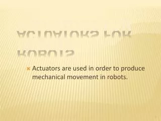
Equations • Solutions • Implementation • Predict the maximum acceleration of the object motion that the robot still can achieve a successful catch • Calculate the size of the end-effector in order to overcome the maximum acceleration of the moving objects
Experimental Validation • Setup • Two types of end-effector (bowl, two scoopers with different width). • Three types of interference (wind, bump, ramp) • Results • With wind interference
Experimental Validation • with bump interference, weighted corner • with bump interference, balanced
Experimental Validation • with ramp interference, weighted corner • with ramp interference, balanced
Third part: A Novel Pneumatic Three-finger Robot Hand
Related work • Three different types of robot hands • Electric motor powered hands, for example: • A. Ramos et. al. Goldfinger • C. Lovchik et. al. The robonaut hand • J. Butterfa et. al. DLR-Hand • Barrett hand • Pneumatically driven hands: • S. Jacobsen et. al. UTAH/M.I.T. hand • Hydraulically driven hands: • D. Schmidt et. al. Hydraulically actuated finger • Vision-based robot hand research • A. Morales et. al. presented a vision-based strategy for computing three-finger grasp on unknown planar objects • A. Hauck et. al. Determine 3D grasps on unknown, non-polyhedral objects using a parallel jaw gripper
Novel pneumatic hand • Disadvantages of current robot hands • Most robot hands are heavy • Even with visual guidance, the robot hand can only grasp stationary objects • Novel hand architecture • build-in pneumatic line in Staubli RX130 • Paper tube, music steel wire embedded inside • Camera mount adjusting “finger” spread angle • 120 degrees between each other
Novel pneumatic hand • Close position Open position • Our research here is to demonstrate that we use a novel idea to built a flexible end effector and it can grasp semi-randomly moving objects. This is not a new type of complex research tool-type robot hands.
ball track robot y x initial hand position final hand position Grasping research • Problem statement
Grasping research • Position prediction • Same as the method in the second part work of this research • Orientation adjustment • Line fitting to get the final “roll” angle • equations
Conclusions: timing model • A generic timing model for a robotic system using visual sensing, where the camera provides the desired position to the robot controller. • We demonstrate how to obtain the values of the parameters in the model, using our camera network workcell as an example. • Implementation to let our industrial manipulator intercept a moving object. • Experimental results indicate that our model is highly effective, and generalizable.
Conclusions: dynamic manipulation • Based on the timing model, we present a novel generic and simple theory to quantify the dynamic intercept ability of vision based robotic systems. • We validate the theory by designing 15 sets of experiments (1050 runs), using two different end effectors under three different interference. • The experimental results demonstrate that our theory is effective.
Conclusions: novel pneumatic hand • A novel pneumatic three-finger hand is designed and demonstrated. • It is simple, light and effective. • Experimental results demonstrate that this novel pneumatic hand can grasp semi-randomly moving objects. • Advantages • The compliance from pneumatics will allow the three-finger hand to manipulate more delicate and fragile objects. • In the experiments of grasping moving objects, unlike the traditional gripper, the contact position for this continuous finger is not very critical, which leaves more room for sensing error.
Sponsors • The South Carolina Commission on Higher Education • The Staubli Corporation • The U.S. Office of Naval Research
ramp interference bump interference The distribution of |vi – vavg | in the balance ramp and bump cases.
Determining the Values • An external camera to observe operation • A conveyor moving in a fixed path at a constant velocity • A light bulb as a tracking object • A laser mounted in the end effector of the robot