Download
1 / 40
400 likes | 522 Vues
Office of Science. Supported by. Macroscopic Stability Research on NSTX and a ReNeWed Future. College W&M Colorado Sch Mines Columbia U Comp-X General Atomics INEL Johns Hopkins U LANL LLNL Lodestar MIT Nova Photonics New York U Old Dominion U ORNL PPPL PSI Princeton U SNL

E N D
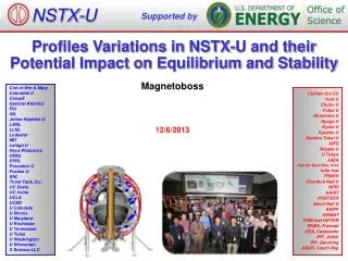
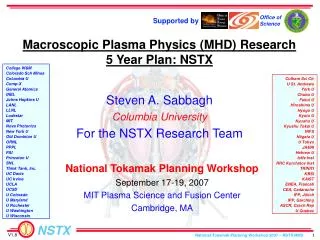
Office of Science Supported by Macroscopic Stability Research on NSTX and a ReNeWed Future College W&M Colorado Sch Mines Columbia U Comp-X General Atomics INEL Johns Hopkins U LANL LLNL Lodestar MIT Nova Photonics New York U Old Dominion U ORNL PPPL PSI Princeton U SNL Think Tank, Inc. UC Davis UC Irvine UCLA UCSD U Colorado U Maryland U Rochester U Washington U Wisconsin S.A. Sabbagh1, R.E. Bell2,J.W. Berkery1, J.M. Bialek1, S.P. Gerhardt2, R. Betti3, D.A. Gates2, B. Hu3, O.N. Katsuro-Hopkins1,B. LeBlanc2, J. Levesque1, J.E. Menard2, J. Manickam2, K. Tritz4, and the NSTX Research Team 1Department of Applied Physics, Columbia University, New York, NY, USA 2Plasma Physics Laboratory, Princeton University, Princeton, NJ, USA 3University of Rochester, Rochester, NY, USA 4Johns Hopkins University, Baltimore, MD, USA Columbia APAM Plasma Physics Colloquium February 6, 2009 Columbia University, New York, NY Culham Sci Ctr U St. Andrews York U Chubu U Fukui U Hiroshima U Hyogo U Kyoto U Kyushu U Kyushu Tokai U NIFS Niigata U U Tokyo JAEA Hebrew U Ioffe Inst RRC Kurchatov Inst TRINITI KBSI KAIST ENEA, Frascati CEA, Cadarache IPP, Jülich IPP, Garching ASCR, Czech Rep U Quebec v1.1
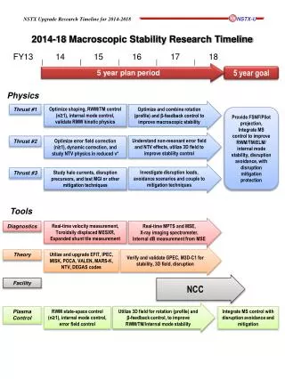
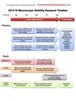
Key Research Challenge: Develop Stability and Control Understanding to Produce Continuous High Beta Plasmas • Motivation • Future spherical torus (ST) magnetic fusion devices plan to run at high ratios of plasma pressure to magnetic field (beta) and with effectively continuous operation • Mega-Ampere level high beta ST plasmas have been reached • Attention now turns to stability physics understanding and mode control to maximize steady-state high beta conditions, minimize beta excursions, and largely eliminate disruptions • Outline • Present macroscopic stability research on NSTX • Related research / device upgrades planned for next five years • Developing longer-term "ITER-era“ research plan through DOE's ReNeW process • community input strongly encouraged • conduits for your input and collaborative discussion
Understanding what profiles and control systems are needed for burning plasmas best occurs before such devices are built • FESAC US ST mission: • Develop compact, high b, burning plasma capability for fusion energy • Stability Goal (in one sentence) • Demonstrate reliable maintenance of high bN with sufficient physicsunderstanding to extrapolate to next-step devices • Knowledge base needed to bridge to these devices; + physics for ITER • Demonstration = Control(of modes and plasma profiles): • Need to determine what control is needed before CTF • Understanding = Vary parameters (+operate closer to burning plasma levels): • Collisionality: influences Vf damping • Shaping: • Plasma rotation level, profile: • q level, profile: • CTF:bN = 3.8 – 5.9 (WL = 1-2 MW/m2) ST-DEMO:bN ~ 7.5 • Both at, or above ideal no-wall b-limit; deleterious effects occur below bNno-wall • high bN accelerates neutron fluence goal - takes 20 years at WL = 1 MW/m2) } All influence b-limiting modes: Kink/ballooning, RWM, NTM
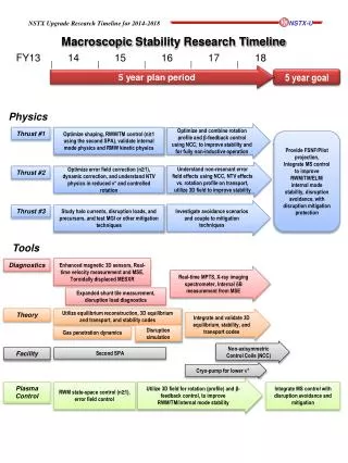
Development of device hardware empowers fundamental stability understanding for robust extrapolation to next-step STs • Operate at parameters closer to burning plasma (e.g. order of magnitude lower ni (PTRANSP) ) • High plasma shaping (k ~ 3), low li operation • Vertical stability, kink/ballooning stability, coupling to passive stabilizers • Resistive wall mode (RWM) stabilization • Understand physics of passive mode stabilization vs. Vf at reduced ni • Non-axisymmetric field-induced viscosity • Non-resonant and resonant, due to 3-D fields and modes at reduced ni • Control modes and profiles, understand key physics • Dynamic error field correction (DEFC) • Demonstrate sustained Vf with reduced resonant field amplification, under Vf profile control • Resistive wall mode control • Increase reliability of active control, investigate multi-mode RWM physics under Vf, q control • Tearing mode / NTM • Stabilization physics at low A, mode locking physics under Vf, q control • Plasma rotation control • Sources (2nd NBI, magnetic spin-up) and sink (non-resonant magnetic braking) • Mode-induced disruption physics and prediction/avoidance • New center stack (Bt = 1T, Ip = 2 MA) • - Liquid Li divertor • - 2nd NBI (incr.) • Singly-powered RWM control coils • RWM coil upgrade (incr.)
Plasma equilibrium goal to access and maintain stable high bN at high shaping • Progress • Central coil PF1A modified (2005) to allow high shaping • Sustained k < 2.7, d < 0.8; transient k = 3 with record shaping factor, SIºq95(Ip/aBt)= 41 • Note: Present CTF design has k = 3.07, lower SI • Highest k and SI plasmas reached bN ~ 6 in 2008 • Plan summary 2009-2011 • Assess/utilize feedback control using real-time EFIT and NBI power to avoid fast kink/ballooning disruptions • Conduct experiments/analysis to maintain high SI plasmas into wall-stabilized, high N > 6 operating space • Plan summary 2012-2013 • Real-time MSE for evaluation of q in real-time EFIT • Utilize/analyze b feedback using stability models; q profile control with 2nd NBI (incremental) • Study ST-CTF target shapes (increased A) at low ni with favorable profiles, determine sensitivity to variations in li, d 121241 t=275ms D.A. Gates, et al., Nucl. Fusion47, 1376 (2007).
RWM sensors (Br) Stabilizer plates RWM sensors (Bp) RWM active stabilization coils NSTX equipped for passive and active RWM control • Stabilizer plates for kink mode stabilization • External midplane control coils closely coupled to vacuum vessel • Varied sensor combinations used for feedback • 24 upper/lower Bp: (Bpu, Bpl) • 24 upper/lower Br: (Bru, Brl)
6 4 2 0 20 10 0 12 8 4 0 500 -500 0.0 0.2 0.4 0.6 0.8 1.0 1.2 Active RWM control and error field correction maintain high bN plasma • n = 1 active, n = 3 DC control • n = 1 response ~ 1 ms < 1/gRWM • bN/bNno-wall = 1.5 reached • best maintains wf • NSTX record pulse lengths • limited by magnet systems • n > 0 control first used as standard tool in 2008 • Without control, plasma more susceptible to RWM growth, even at high wf • Disruption at wf/2p ~ 8kHz near q = 2 • More than a factor of 2 higher than marginal wf with n = 3 magnetic braking Without control With control bN bN > bNno-wall bNno-wall = 4 (DCON) wf/2p (kHz) 129283 wf maintained 129067 DBpu,ln=1(G) IA (A) n = 1 feedback n = 3 correction t(s) (Sabbagh, et al., PRL 97 (2006) 045004.)
Probability of long pulse and <bN>pulse increases significantly with active RWM control and error field correction • Standard H-mode operation shown • Ip flat-top duration > 0.2s (> 60 RWM growth times) Control off (908 shots) Control on Control on (114 shots) Control off Frequency distribution Ip flat-top duration (s) • Control allows <bN>pulse > 4 • bN averaged over Ip flat-top
0.5 0 -0.5 -1.0 -1.5 20 10 0 300 200 100 0 10 0 -10 0.606 0.610 0.614 0.618 1 1 During n=1 feedback control, unstable RWM evolves into rotating global kink • RWM grows and begins to rotate • With control off, plasma disrupts at this point • With control on, mode converts to global kink, RWM amplitude dies away • Resonant field amplification (RFA) reduced • Conversion from RWM to rotating kink occurs on tw timescale • Kink either damps away, or saturates • Tearing mode can appear during saturated kink IA(kA) RFA DBpn=1(G) RFA reduced RWM Mode rotation Co-NBI direction fBpn=1(deg) DBn=odd(G) 128496 t (s)
2 1 0.608 0.610 0.612 0.614 0.616 Soft X-ray emission shows transition from RWM to global kink Transition from RWM to kink Tearing mode appears during kink RWM onset time + 35 ms edge edge q = 2 core spin-up RWM kink core edge 0.645 0.646 t (s) • Initial transition from RWM to saturated kink • Tearing mode appears after 10 RWM growth times and stabilizes filtered 1 < f(kHz) < 15 core 128496 t (s)
6 4 2 0 15 10 5 0 30 20 10 0 1.0 0 -1.0 15 10 5 0 0.0 0.2 0.4 0.6 0.8 1.0 1.2 t(s) Low wf, high bN plasma not accessed when feedback response sufficiently slowed • Low wf access for ITER study • use n = 3 braking • n = 1 feedback response speed significant • “fast” (unfiltered) n = 1 feedback allows access to low Vf, high bN • “slow” n = 1 “error field correction” (75ms smoothing of control coil current) suffers RWM at wf ~ 5kHz near q = 2 bN fast feedback slow feedback wf/2p (kHz) DBpln=1(G) RWM IA (kA) n = 3 braking n = 3 correction 130639 130640 DBrun=1(G)
6 4 2 0 15 10 5 0 30 20 10 0 1.0 0 -1.0 15 10 5 0 0.0 0.2 0.4 0.6 0.8 1.0 1.2 t(s) Low wf, high bN plasma not accessed when two feedback control coils are disabled • Low wf access for ITER study • use n = 3 braking • n = 1 feedback doesn’t stabilize plasma with 2 of 6 control coils disabled • scenario to simulate failed coil set in ITER • Feedback phase varied, but no settings worked • RWM onset at identical time, plasma rotation bN 2 control coils out feedback phase varied All coils on wf/2p (kHz) DBpln=1(G) RWM IA (kA) braking and feedback n = 3 correction 130641 130640 130642 130643 DBrun=1(G)
Experimental bN reached Experiment (control off) (control on) unstable stable unstable DCON no-wall limit 45 225 290 315 mode rotating passive with- wall limit active control g (1/s) g (1/s) mode locked active feedback (reached) passive Dff (deg) bN adv. controller Experimental RWM control performance consistent with theory • VALEN code with realistic sensor geometry, plasmas with reduced Vf • Feedback phase scan shows superior settings
Significant bN increase expected by internal coil proposed for ITER • 50% increase in bN over RWM passive stability ITER VAC02 stabilization performance ITER VAC02 design (40° sector) passive Growth rate (s-1) all coils midplane coils upper+ lower coils VALEN-3D bN 3 toroidal arrays, 9 coils each
Design work for upgraded non-axisymmetric control capabilities has begun • Capabilities • Non-axisymmetric control coil (NCC) – at least four applications • RWM stabilization (n > 1, higher bN) • DEFC with greater field correction capability • ELM control (n = 6) • n > 1 propagation, increased Vf control) • Similar to proposed ITER coil design • In incremental budget • Addition of 2nd SPA power supply unit for simultaneous n > 1 fields • Non-magnetic RWM sensors; advanced RWM active feedback control algorithms • Alteration of stabilizing plate connections Proposed Internal Non-axisymmetric Control Coil (NCC) (initial designs - 12 coils toroidally) RWM with n > 1 RWM observed Secondary PP option (Sabbagh, et al., Nucl. Fusion 46, 635 (2006). ) Existing coils Primary PP option
VALEN computed RWM stability for proposed RWM control coils upgrade - behind passive plates (PP) Stainless Steel Plates Copper Plates Coils behind SS secondary PP Coils behind secondary PP Coils behind SS primary PP Coils behind primary PP growth rate g [1/s] growth rate g [1/s] Ideal wall limit Ideal wall limit External coils External coils passive passive bN bN • coils behind copper passive plates perform worse than existing external RWM coil set • change copper passive plates to SS RWM performs better than existing external coil set (note: idealized sensors used)
external coils growth rate g [1/s] growth rate g [1/s] Ideal wall limit Ideal wall limit external coils passive bN bN Proposed control coils on plasma side of copper passive plates computed to stabilize to 99% of bNwall VALEN coils on plasma side Cu secondary PP stabilize to bN = 7.04 coils on plasma side Cu primary PP stabilize to bN = 7.05 Ideal wall limit bN = 7.06 (note: idealized sensors used)
Modification of Ideal Stability by Kinetic theory (MISK code) investigated to explain experimental RWM stabilization • Simple critical wf threshold stability models or loss of torque balance do not describe experimental marginal stability • Kinetic modification to ideal MHD growth rate • Trapped and circulating ions, trapped electrons • Alfven dissipation at rational surfaces • Stability depends on • Integrated wf profile: resonances in dWK (e.g. ion precession drift) • Particle collisionality Sontag, et al., Nucl. Fusion 47 (2007) 1005. Hu and Betti, Phys. Rev. Lett 93 (2004) 105002. wf profile (enters through ExB frequency) Trapped ion component of dWK (plasma integral) Energy integral precession drift bounce collisionality
wf/wfexp wf/wfexp gtw Kinetic modifications show decrease in RWM stability at relatively high Vf – consistent with experiment Theoretical variation of wf RWM stability vs. Vf (contours of gtw) wf/wfexp Marginally stable experimental profile 2.0 wf/2p (kHz) 1.0 2.0 Im(dWK) 121083 0.2 1.0 y/ya 0.2 experiment • Marginal stable experimental plasma reconstruction, rotation profile wfexp • Variation of wf away from marginal profile increases stability • Unstable region at low wf unstable Re(dWK)
wf/wfexp Kinetic model shows overall increase in stability as collisionality decreases Increased collisionality (x6) Reduced collisionality (x1/6) wf/wfexp gtw gtw 2.0 Im(dWK) 2.0 1.0 0.2 0.2 1.0 unstable unstable Re(dWK) Re(dWK) • Vary n by varying T, n at constant b • Simpler stability dependence on wf at increased n • Increased stability at wf/wfexp ~ 1 • Unstable band in wf at increased wf
Hot ions have a strongly stabilizing effect on DIII-D without hot ions with hot ions • MISK show band of instability at moderate rotation without hot ions, but complete stability with hot ions: D(gtw) ~ 1.0 • DIII-D shot 125701 @ 2500ms and rotation from 1875-2600ms • This may explain why DIII-D is inherently more stable to the RWM than NSTX • energetic particle modes might “trigger” RWM by fast particle loss (JT-60U IAEA 08) (J.W. Berkery, Mode Control Mtg. 2008)
NSTX RWM stability with hot ions under evaluation Ptot 121083 Pfast High level of Pfast in NSTX Pfast Pressure (kPa) unstable Variation due to Pfast • Direct effect on calculated growth rate using test profiles (based on TRANSP analysis) for hot ion pressure: D(gtw) ~ 0.2 • Stability using TRANSP runs of RWM marginally stable plasmas now underway • TRANSP hot ion population smaller at edge in NSTX vs. DIII-D – may explain why RWM apparently less stable in NSTX
Lithium wall conditioning, n=1 RWM control, n=3 error correction also shown to control (eliminate) tearing modes • Physics of tearing mode elimination still under investigation • Full suppression of modes not seen on all shots • If lithium wall conditioning a key element, liquid lithium divertor might be used for NTM control • MHD spectrogram w/o n=1 feedback and n=3 correction • MHD spectrogram with lithium, n=1 feedback and n=3 correction n=1 mode drops No MHD, and rotation maintained CHERS vt at R = 139cm Red with control Black w/o control Red with control Black w/o control
Required drive for NTM onset better correlated with rotation shear than rotation magnitude NTM Drive at Onset Only Poorly Correlated with q=2 (Carbon) Rotation NTM Drive at Onset Better Correlated with Local Flow Shear • For fixed Vf, order of increasing onset drive: EPM triggers, ELM triggers, and “Triggerless” • All trigger types have similar dependence on flow shear • Dependence likely to related to intrinsic tearing stability, not triggering S.P. Gerhardt, submitted to Nucl. Fusion
New 2nd NBI RTAN=110,120,130cm Present NBI RTAN=50,60,70cm 2nd NBI and BT = 1T with center stack upgrade to be used for study and control MHD modes (and much more…) • Fully non-inductive scenarios require 2nd NBI (7-10MW of NBI heating) for H98 1.2 • tCR will increase from 0.35 1s if Te doubles at lower ne, higher BT • Need 3-4 tCR times for J(r) relaxation 5s pulses need 2nd NBI • qmin > key rationals 1.5, 2 to be used for NTM control Above: N=5, T=10%, IP=0.95MA N=6.1, T=16%, qmin > 1.3, IP=1MA at BT=0.75T possible
Establish predictive physics understanding of NTMS • 2009-2011: Compete Characterization of NTM Onset, Small Island Physics, Restabilization • Characterize the role of Vf and the ideal kink limit on NTM onset thresholds • Characterize triggering events, including sawtooth triggered 3/2 modes and “triggerless” NTMs with qmin > 1 • Finish characterization of the marginal island width for 2/1 and 3/2 modes, including comparisons to conventional aspect ratio devices • Understand details of how Li conditioning and DEFC assist in stabilizing 2/1 modes • 2009-2011: Establish a program of relevant NTM modeling • Implement PEST-III calculations of ’ for realistic NSTX equilibria, including the effects of nearby rational surfaces • Utilize initial value codes like NIMROD for more sophisticated treatment of transport near the island or rotation shear effects on mode coupling and island eigenfunction. • 2012-2013: Develop scenarios that mitigate/eliminate deleterious NTM activity • Quantify the benefits of qmin > 2 operation, and the role of higher order (3/1, 5/2) modes in this case • Utilize increased toroidal field (new center stack) to scale rqi in single device • Utilize 2nd beamline for current profile control, possibly allowing ’ stabilization of NTMs even with qmin < 2 Collaborations are an essential element of research plan (GA, AUG, JET, U. of Tulsa,…)
4 3 2 1 0 0.9 1.1 1.3 1.5 Non-axisymmetric field-induced neoclassical toroidal viscosity (NTV) important for low collisionality ST-CTF, low rotation ITER plasmas • Significant interest in plasma viscosity by non-axisymmetric fields • Physics understanding needed to minimize rotation damping from ELM mitigation fields, modes (ITER, etc.) • NTV investigations on DIII-D, JET, C-MOD, MAST, etc. • Expand studies on NSTX • Examine larger field spectrum • Improve inclusion of plasma response using IPEC • Consider developments in NTV theory • Reduction, or saturation due to Er at reduced ion collisionality, multiple trapping states, bounce/precession resonances, superbanana regime, etc. • Some effects suggest continued increase in viscosity at reduced ni • Examine NTV from magnetic islands Measured d(IWp)/dt profile and theoretical NTV torque (n = 3 field) in NSTX) W. Zhu, et al., Phys. Rev. Lett.96, 225002 (2006). No Vf shielding in core; used Shaing erratum measured TNTV (N m) e.g. A.M. Garofalo, APS 2008 invited (DIII-D) theory axis R (m) Dominant NTV Force for NSTX collisionality… J.K. Park, APS 2008 invited talk …will it saturate, decrease at lower ni ? Can examine at order of magnitude lower ni with center stack upgrade
0 3 2 -5 -10 1 0.4 0.5 0.6 0.7 -15 0 Stronger non-resonant braking at increased Ti 0.0 • Observed non-resonant braking using n = 2 field • Examine Ti dependence of neoclassical toroidal viscosity (NTV) • Li wall conditioning produces higher Ti in region of high rotation damping • Expect stronger NTV torque at higher Ti (-dwf/dt ~ Ti5/2 wf) • At braking onset, Ti ratio5/2 = (0.45/0.34)5/2 ~ 2 • Consistent with measured dwf/dt in region of strongest damping 130720 n = 2 braking Icoil (kA) 130722 -0.4 -0.8 4 wf (kHz) no Li Li wall 2 R = 1.37m 0.4 0.3 Ti (keV) Li wall no lithium 0.2 0.1 t (s) Damping profiles (Ti ratio)5/2 No Li (1/wf)(dwf/dt) Li wall 2x 0.9 1.1 1.3 1.5 0.9 1.1 1.3 1.5 R(m) R(m)
30 20 10 0.9 1.0 1.1 1.2 1.3 1.4 1.5 1.6 0 1.0 1.1 1.2 1.3 1.4 1.5 1.6 n = 2 non-resonant braking evolution distinct from resonant • Resonant: • Clear momentum transfer across rational surface • evolution toward rigid rotor core • Local surface locking at low wf • Non-resonant: • broad, self-similar reduction of profile • Reaches steady-state (t = 0.626s) Steady-state profile (from non-resonant braking) t = 0.626s (Dt = 10 ms) t = 0.466s (Dt = 10 ms) bN ~ 3.5 t = 0.516s outward momentum transfer wf(kHz) t = 0.816s 128882 128882 R(m) R(m)
High b ST research plan focuses on bridging the knowledge gaps to next-step STs; contributes to ITER • Macroscopic stability research direction • Transition from establishing high beta operation to reliably and predictably sustaining and controlling it – required for next step device • Research provides critical understanding for tokamaks • Stability physics understanding applicable to tokamaks including ITER, leveraged by unique low-A, and high b operational regime • Specific ITER support tasks • NSTX provides access to well diagnosed high beta ST plasmas • 2009-2011: allows significant advances in scientific understanding of ST physics toward next-steps, supports ITER, and advances fundamental science • 2012-2013+: allows demonstration/understanding of reliable stabilization/profile control at lower collisionality – performance basis for next-step STs
DOE ReNeW process to define “ITER-era” (20 yr) research program • ReNeW: Research Needs Workshop • To inform the Office of Fusion Energy Sciences (OFES) in preparing a strategic plan for research in each major area of the Fusion Energy Sciences Program • To allow U.S. fusion community to explain research goals, methods to achieve them • Including communication to new administration • MAIN WEB PAGE: http://burningplasma.org/renew.html • Document • Vol 1: Define scientific research needed to fill “gaps” in present understanding • “gaps” defined in / modified from Greenwald report, FESAC TAP reports • Divided into 5 “themes” comprising magnetic fusion research • Vol 2: Define (~ 15) “research thrusts” that will carry out this research • Basis for detailed program plan to be constructed by OFES
ReNeW organized into 5 fusion research themes Spherical Torus sub-theme Structure/gaps FESAC Toroidal Alternates Panel Report Structure/gaps Energy Policy Act task group report Structure/gaps Priorities, Gaps, and Opportunities Panel Report (“Greenwald Report”) Reports available at: http://burningplasma.org/renew.html
ReNeW ST Panel is on Schedule to Complete Tasks • Tasks through March 16-19 Workshop • Solicit community input: (First call for input DONE – continue to engage community) • Review issues as described in TAP panel report: (DONE: embodied in community distributed draft of ST section V1.7) ********** WE ARE HERE ********** • Identify scientific research needed to address the issues • Review and expand on research outlined in the TAP panel report • Draft write-up of research requirements, make available to community • Fold in community input on research requirements • Develop draft “research thrusts” for discussion at March workshop • FESAC TAP Report Mission statement: Establish the ST knowledge base to be ready to construct a low aspect ratio component testing facility that provides high heat flux, neutron flux, and duty factor needed to inform the design of a demonstration fusion power plant.
Interpretation of the FESAC TAP document by some people in the community • Pros • ST-CTF focus • Cons • Alienates a significant part of the community (research plan has been characterized by some (to quote) as a “dead end”), so loses potential constituency • Many have complained that several physics issues have been “swept under the rug”, even at the level of an ST-CTF device • Interpreted as above, it doesn’t maximize cross-cutting with other magnetic fusion research Present STs (Research informing DEMO) ST-CTF DEMO Key point: Let’s engage the community and make appropriate, small changes to strengthen these weak points.
(STRAWMAN) U.S. ST Research Vision consistent with Present ST Mission Statement Research Scientific Research during ITER era informing DEMO • Tier 1 • Start-up and Ramp-up • Plasma-material interface • Electron energy transport • - Magnets • Tier 2 • Stability & SS Control; 3D fields • Disruptions • Heating & current drive • Ion-scale transport • - Fast particle instabilities • Tier 3 • NTMs • Continuous NBI systems Present STs DEMO Upgraded ST Facilities Potential application Potential application ST Performance Extension Facility ? ST-CTF Fusion/Fission Hybrid driver • Blanket development (magnetic, inertial fusion) • Fusion materials development • Nuclear waste processing • … Facilities and Applications ReNeW ST Panel v1.2
Several Conduits for Participation in ReNeW Process • ReNeW Forum (web bulletin board) • Contribute to open discussions; start your own discussions • Registration instructions: http://burningplasma.org/forum/ • Request authorization to ReNeW Forum: e.g. email: sabbagh@pppl.gov • ST topic: https://burningplasma.org/forum/index.php?showforum=114 • ST Group: Direct input to/discussion of evolving draft ST section of document • Posted: https://burningplasma.org/forum/index.php?showtopic=653 • Submit short white papers describing your ideas on how to resolve key issues, support/define research thrusts • Download directions at: http://burningplasma.org/renew.html • Participate in March 2009 Workshops • Links to websites with info/registration at: http://burningplasma.org/renew.html • Directly contact panel members • ST Group: 10 Panel members (see next page); more than 30 advisors
ReNeW Spherical Torus Panel Members • Contact any panel member for authorization to access the ReNeW Forum (website bulletin board) • Full advisor list posted at: https://burningplasma.org/forum/index.php?showtopic=636
NSTX Disruption Studies Contribute to ITER, Aim to Predict Disruption Characteristics & Onset For Future Large STs Halo Current Magnitudes and Scaling Area-normalized (left), Area and Lext-normalized (right) Ip quench time vs. toroidal Jp (ITER DB) 2006 Instrumentation 2008 Instrumentation Lower Center Stack Vessel Bottom Near CHI Gap Inner to Outer Vessel Outboard Divertor Area Normalized Quench Time (msec/m2) Max Halo Current Magnitude (kA) NSTX Pre-Disruption Current Density (MA/m2) (MA2/T) • Fastest NSTX disruption quench times of 0.4 ms/m2, compared to ITER recommended minimum of 1.7 msec/m2. • Reduced inductance at high-, low-A explains difference • New instrumentation in 2008 yields significant upward revision of halo current fractions • reveals scaling with IP and BT. • Mitigating effect: Largest currents for deliberate VDEs • Toroidal peaking reduced at large halo current fraction. Expand these Results For a Complete Characterization of Disruption Dynamics, Including Prediction Methods
Understand the Causes and Consequencs of Disruptions for Next-step STs and ITER • 2009-2012: Halo current characterization • Install arrays of instrumented tiles in outboard divertor, measure currents into LLD trays (2009-10) • Utilize CS upgrade to instrument inboard divertor tiles (2011) • Understand the halo current paths, toroidal peaking physics, and driving mechanisms, in order to make predicitons for future ST plasmas • 2009-2011: Thermal quench characterization • Determine the fraction of stored energy lost in the thermal quench, compared to that in the pre-disruption phase, over a variety or plasmas and disruptions • Utilize fast IR thermography to understand time-scale and spatial distribution of the thermal quench heat flux • Predict the impulsive heat loading constraints on future ST PFCs • 2010-2013: Learn to predict and prevent disruptions • Develop real-time diagnostics useful for predicting impending disruptions for relevant ST equilibria and instabilities • Test predictive algorithms, to determine the simplest, most robust prediction methods • Use in conjunction with stability models and mode control systems developed