Cervical Spine Trauma
Cervical Spine Trauma. Aaron B. Welk , DC Resident, Department of Radiology Logan College of Chiropractic. Three Column Model. Anterior ALL Anterior half of vertebral body, disc, and supporting soft tissues Middle PLL Posterior half of vertebral body, disc, and supporting soft tissues

Cervical Spine Trauma
E N D
Presentation Transcript
Cervical Spine Trauma Aaron B. Welk, DC Resident, Department of Radiology Logan College of Chiropractic
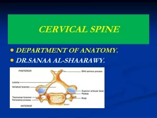
Three Column Model • Anterior • ALL • Anterior half of vertebral body, disc, and supporting soft tissues • Middle • PLL • Posterior half of vertebral body, disc, and supporting soft tissues • Posterior • Posterior elements • Facet joints • Associated soft tissues
Three Column Model • Disruption of only one column is generally stable • Disruption of 2 or 3 columns implies instability • Flexion and extension films may highlight instability that is not evident on neutral lateral.
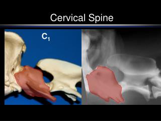
Evaluation Of Alignment Instability may be subtle. Disruption of any one of the anatomical lines may indicate injury. Evaluation of 4 lines must be done on all lateral films. Anterior body line (A) Posterior body line (B) Spinolaminar line (C) Posterior spinous line
Flexion Injury • Unilateral Locked Facet • Flexion with rotation • Most common location is C4/5 and C5/6 • Little or no body displacement • Bow-tie Sign • Bilateral Locked Facet • Flexion with enough force to distract facets • 50% anterolisthesison lower segment
Bilateral Locked Facet Left Right
Bilateral Locked Facet Sag STIR Sag T2 FSE
Spinal Cord Contusion • Non-Hemorrhagic bruising of spinal cord • MRI Appearance: • T1: Low signal intensity • T2: High signal intensity
Spinal Cord Hemorrhage • Hyperacute: • T1: isointense • T2: high signal intensity • Acute: • T1: Low signal intensity • T2: Low signal intensity • Subacute (early): • T1: high signal intensity • T2: low signal intensity • Subacute (late): • T1: high signal intensity • T2: high signal intensity • Chronic: • T1: isointense • T2: high signal intensity
Spinal Cord Hemorrhage T1 T2
Flexion Injury • Anterior Wedge Compression • Usually Stable unless posterior ligaments are disrupted • Disrupted posterior elements may appear stable initially due to muscle spasm • Teardrop Burst • Most severe injury compatible with life. • 80% with neurologic injury • Posterior body is displaced into neural canal
Clay-Shoveler’s Fracture • Oblique Fracture through the spinous process of C6-T3 (C6 and C7 are most common) • The name is derived from the common occurrence of this fracture in Australian clay miners. • Usually caused by hyperflexion, although a direct blow can also cause this injury
Extension Injury • Extension Teardrop • Avulsion of ALL from inferior corner of vertebral body • Usually at C2 or C3 • Hangman’s Fracture • Fracture of the neural arch of C2 with varying degrees of C2/3 disk involvement • Type I- Fracture of neural arch w/o disk involvement • Type II- >3mm displacement or 15˚ angulation at C2/3 • Type III- Anterior displacement of C2 due to unilateral or bilateral facet dislocation. • Pillar/Facet Fracture • Extension injury while head is rotated
Odontoid Fractures • Mechanism of injury is not fully understood and experimental attempts to recreate have been unsuccessful. • Injury is result of major force and usually results from MVA or falls. • 3 Classifications: • Type I- Fracture of upper portion of dens (Stable) • Type II- Fracture at base of dens at C2 body junction (Unstable) • Type III- Fracture into C2 body (Stable)*
Jefferson’s (Burst) Fracture • Ring fracture of C1 due to axial loading • Lateral displacement of lateral masses • May have little or no neurologic deficit unless transverse ligament is ruptured
References • Musculoskeletal Imaging: The Requisites, 3rd ed. B.J. Manaster, David G. Disler, David A. May, editors. St. Louis: Mosby; 2007. pp 164-174 • Diagnosis of Bone and Joint Disorders. 4th ed. Donald Resnick. Philadelphia: W.B. Saunders; 2002. pp 2958-2981
Images • http://thejns.org • http://radiographics.rsna.org • http://download.imaging.consult.com • www.medcyclopedia.com • http://emedicine.medscape.com • http://handbook.muh.ie • http://int.prop.if2.cuni.cz • http://radiologyinthai.blogspot.com • www.aafp.org • www.learningradiology.com • http://img.orthobullets.com • http://img04.webshots.com • www.mypacs.net • www.medifax.com • www.medscape.com • http://gentili.us • www.med.wayne.edu • www.radiologyassistant.nl