Download
1 / 20
200 likes | 403 Vues
NSTX. Supported by. High Harmonic Fast Wave Progress and Plans. College W&M Colorado Sch Mines Columbia U CompX General Atomics INL Johns Hopkins U LANL LLNL Lodestar MIT Nova Photonics New York U Old Dominion U ORNL PPPL PSI Princeton U Purdue U SNL Think Tank, Inc.

E N D
NSTX Supported by High Harmonic Fast WaveProgress and Plans College W&M Colorado Sch Mines Columbia U CompX General Atomics INL Johns Hopkins U LANL LLNL Lodestar MIT Nova Photonics New York U Old Dominion U ORNL PPPL PSI Princeton U Purdue U SNL Think Tank, Inc. UC Davis UC Irvine UCLA UCSD U Colorado U Maryland U Rochester U Washington U Wisconsin Gary Taylor, PPPL for the NSTX Team Culham Sci Ctr U St. Andrews York U Chubu U Fukui U Hiroshima U Hyogo U Kyoto U Kyushu U Kyushu Tokai U NIFS Niigata U U Tokyo JAEA Hebrew U Ioffe Inst RRC Kurchatov Inst TRINITI KBSI KAIST POSTECH ASIPP ENEA, Frascati CEA, Cadarache IPP, Jülich IPP, Garching ASCR, Czech Rep U Quebec 27th NSTX Program Advisory Committee Meeting (PAC-27) LSB-318, PPPL February 4, 2010
Outline • Role of HHFW in NSTX Program • Recent Advances in HHFW Research & Modeling • Research Plan for 2010-12
HHFW Heating & Current Drive (CD) Developed forNon-Inductive Ramp-up, Bulk Heating & q(0) Control • Ultimately Spherical Torus needs to run non-inductively Non-Inductive Strategy HHFW Goals IP Target [kA] (1) HHFW couples to start-up plasma (2) HHFW forIPoverdrive through bootstrap & HHFW CD (3) HHFW generates sufficient IP to confine NBI ions (4)HHFW provides bulk heating & q(0) control in H-mode ~750 ~500 ~300 H-mode Time (3) HHFW + NBI (2) HHFW (4) Sustain with HHFW + NBI CHI, PF, Guns
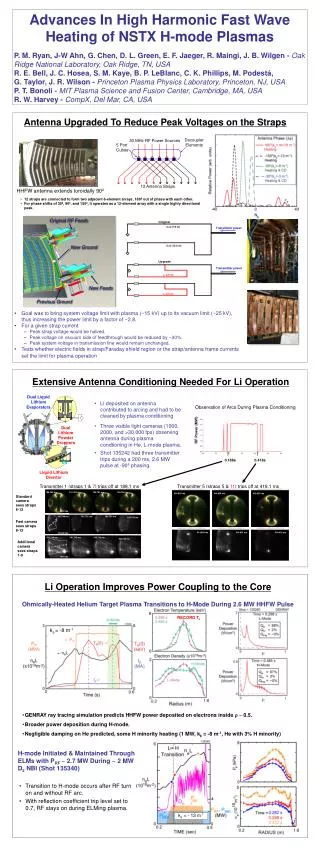
HHFW Double End-Fed Upgrade Installed in 2009 Shifts Ground from End to Strap Center Original RF Feeds • Designed to bring system voltage limit with plasma (~15 kV) to limit in vacuum (~25 kV): • Increases PRF ~ 2.8 times • While Li pumping improves rf coupling, arcs occur when rf currents in straps ablate Li on antenna, driving Li into the high voltage regions inside antenna • Use rf plasma conditioning in 2010 to remove Li coating on antenna, increasing arc-free rf power limit New Ground New Feeds Previous Ground • Electronic ELM/arc discrimination system to be tested in 2010: • Arc produces faster change in reflected power signal than ELMs
Double End-Fed Antenna Performance in 2009 Significantly Improved Compared to 2008 Operation • Modifications to external transmission line completed in June • Operated RF into plasma during July & August • New antenna reached 2-3 MW more quickly than previous antenna • Improvements likely due to a combination of antenna upgrade andLi conditioning: • Coupled > 4 MW into He L-mode • Record Te(0) ~ 6.2 keV with Prf ~ 2.7 MW • Allowed study of L-H & H-L transitionin He & Dwith RF • Maintained HHFW coupling through L-H transition and during relatively large repetitive ELMs during DNBI-fuelled H-modes • Continue to evaluate new antenna performance in 2010
HHFW Heating of H-Mode Plasmas Less Efficient at Lower kf, Due to Increased Edge Losses During kf = -13 m-1 HHFW heating of NBI H-mode plasmas ~ 1/3 of the rf power is lost outside plasma separatrix The fraction of rf power lost in the edge increases to ~ 2/3 for kf = -8 m-1 HHFW heating A major goal of the NSTX HHFW research is to identify and, if possible, mitigate edge rf power loss mechanisms
New IR Camera Measurements Show Higher RF Power Heat Flux to Divertor for Lower kf Visible Camera IR Camera 3 Pnbi = 2 MW Heat Flux(MW/m2) Prf = 1.8 MW kf = - 8 m-1 Pnbi = 2 MW IR View • "Hot" region in outboard divertor more pronounced at k = - 8 m-1than - 13 m-1 • 3 MW/m2 measured by IR cameraduring 2.6 MW of kf = - 8 m-1 RF heating • Increased visible & IR camera coverage for 2010 campaign Prf = 1.8 MW kf = -13 m-1 Pnbi = 2 MW PAC25-26
Full Wave Model Predicts PRF ~ 100-200 kW Can Drive PDI; PRF Needed to Drive PDI Falls with kf C III Passive Spectroscopic Ti Shows PDI Heating of Edge Ions 1-D Extended Boundary, Nonlinear, AORSA Full Wave Model Shows Dependence of PDI Threshold on kf R=1.50 m (Redge=1.52 m) Poloidal Ti(eV) Relative Amplitude of PDI Generated IBW [G. Chen, ORNL] PAC25-26 PRF = 1.2-1.3 MW • Previously estimated up to 20% of RF power may be lost to PDI • Develop modeling & measurements in 2010-12 to better quantify importance of RF power loss due to PDI
Significant Interaction Between HHFW & NBIFast-Ions Over Multiple Cyclotron Harmonics BT(0) = 5.5 kG Fast-Ion Da (FIDA) Measurements kf = - 8 m-1 • Measured acceleration of NBI fast-ions and large increase in neutron rate during HHFW + NBI plasmas • As predicted originally by CQL3D/GENRAY • Measured significant enhancement & broadening of fast-ion profile when HHFW power is applied PAC25-26
Finite Lamor Radius & Banana-Width Effects Broaden Fast-Ion Profile in NSTX Zero-orbit-width Fokker-Planck CQL3D/GENRAY ray tracing model predicts fast-ion profile peaked on axis Finite-orbit-width Monte- Carlo ORBIT-RF/AORSA 2D full wave model predicts broader outwardly shifted fast-ion profile NBI + HHFW Differences between the ORBIT-RF/AORSA simulation and the FIDA data are being investigated CQL3D modeling with first order orbit-width correction in progress this year A full-finite orbit width version of CQL3D is planned for 2011, but funding for this upgrade is uncertain at this time PAC25-26
HHFW Research Plan for 2010 – (1) • 2010 research milestone to characterize HHFW Heating & CD in D H-mode, and at low Ip • Heating & ramp-up of low Ip plasmas: [1.5(0.5)+1(SFSU)]IOS-5.2 • RF heating of low Ip (~ 200 kA) plasmas • Sustain 100% non-inductive D2 HHFW H-mode • HHFW interactions with ELMs & SOL: [1.5+0.5(ITER)]IOS-5.2 • HHFW power coupling & ELM activity • RF heating in divertor SOL during NBI + RF H-modes • Fast-ion interactions, rotation effects & RFCD: [1(0.5)]IOS-5.2, TC-9 • HHFW heating efficiency of NBI plasmas & fast-ion study • RF clamping of edge rotation • MSE measurement of HHFW CD [ ] = priority 1 run days ( ) = priority 2 run days ITPA task PAC25-6
HHFW Research Plan for 2010 – (2) • Beginning to integrate HHFW into advanced scenarios (ASC TSG): • HHFW pre-heating, lower collisionality targets for improved NBCD& RF generated reversed-shear L-modes [2(0.5)] [ ] = priority 1 run days ( ) = priority 2 run days • 4 days for HHFW plasma conditioning: • 2-day conditioning campaign early in run • 3-4 HHFW experimental campaigns, lasting 3-4 days each, preceded by ~ 1/2 day of conditioning • Plasma conditioning includes machine proposal to assess performance of the double-fed antenna • Improved visible & IR camera imaging of antenna and divertor: • RF/Langmuir probe will be located at or near divertor “hot” streak • Evaluate electronic ELM/arc discrimination to minimize RF trips • Develop extended boundary AORSA & implement first order finite-orbit correction in CQL3D & AORSA • Interviewing candidates for new RF post-doc position PAC25-26
HHFW Research Plan for 2011-12 2011: • Heating & CD operation with NBI H-mode with double fed antenna, arc/ELM discrimination, Li injection & LLD: • Benchmark core CD against advanced RF codes upgraded to include interaction with fast ions & use new tangential FIDA • HHFW couplingduring Ip ramp-up • MSE-LiF to provide q(r) without NBI heating • Prepare for 2010 milestone coupling HHFW into CHI-initiated plasma • RF edge losses significant at low Ip; AORSA needs to include these edge losses, funding probably insufficient to complete this upgrade by 2011 2012: • Milestone: Assess confinement, heating, and ramp-up of CHI start-up plasma (with SFSU TSG) • Complete full-finite orbit width version of CQL3
Summary • Initial operation of the double end-fed antenna was encouraging: • Increased arc-free power capability & produced RF H-modes in He & D • Coupling maintained during NBI through L-H transition & ELMs • Use upgraded antenna & LLD in 2010 to improve coupling in H-modes & low Ip regime – generate 100 % NI fraction in H-mode • Fast-wave interaction with the edge & divertor appear to be an important RF power loss mechanism, particularly at low kf • 2010 expts with improved visible/IR camera coverage & RF probes • HHFW experiments in 2011-12 will study heating & CD in D H-mode & CHI-initiated, HHFW-driven Ip ramp-up • Extended boundary AORSA & finite-orbit upgrade to CQL3D & AORSA being developed in 2010-11
Well Defined Antenna Spectrum Ideal for Controlling Deposition, CD Location & Direction Decoupler Elements RF Power Sources 5 Port Cubes 12 Antenna Straps IP B HHFW antenna extends toroidally 90° • Phase between adjacent straps easily adjusted between = 0°to = 180°
Toroidal Edge Rotation Appears to Lock During RF, Especially at Lower kf Vtor Measured by Charge Exchange Recombination Spectroscopy Mechanism not understood, but may point to edge ion loss RF apparently provides a drag on core plasma rotation as well
AORSA with Boundary Extended Outside Separatrix Predicts More Extensive |ERF| in Scrape-off at Low kf 2-D AORSA Full Wave Model : |ERF| Field Amplitude [D. Green, ORNL] Antenna • Initial 2-D full wave results now being extended to 3-D Preliminary Results
Lithium Wall Conditioning Enabled HHFW to Provide Core Electron Heating Early in Ip Ramp Core HHFW electron heating also measured during CHI start-up HHFW-assisted ramp-up and HHFW heated low Ip experiments planned for 2010
Significant RF Power Deposition on Slowing NBI Ions in Core During H-Mode, Particularly at Lower kf kf = - 8 m-1 Pe = 73% Pfi = 27% kf = - 13 m-1 Pe = 84% Pfi = 16% • Modeling does not include RF acceleration of fast ions