Download
1 / 15
150 likes | 305 Vues
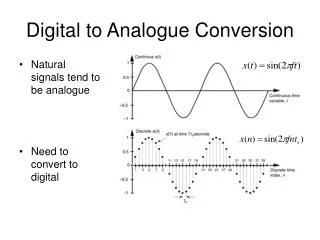
Analogue to Digital Conversion. By Cap’n Tim Johnson, PE Prepared 11/12/2013. Digital World. The digital in A/D conversion consists of binary or hex numbers that will come to stand for a real world phenomenon.

E N D
Analogue to Digital Conversion By Cap’n Tim Johnson, PE Prepared 11/12/2013
Digital World • The digital in A/D conversion consists of binary or hex numbers that will come to stand for a real world phenomenon. • Say, for instance we have four-bits we use to represent an analog value that’s been converted. • In binary, the numbers would range from 0000 to 1111 and there are (24 = 16) sixteen different values represented. • These number in base 10 could range from 0-15
Typical example of converting a binary number to a decimal number While this is very useful in converting binary number to decimal and back… analog to digital conversion is similar but different.
A/D is converting a binary number into something else Something Else We want to change the decimal number column into real world values that don’t necessarily increment by whole numbers but do increment by binary numbers.
This example shows the conversion of real world values to binary numbers Real World Values 0.00 0.33 0.66 1.00 1.33 1.66 2.00 2.33 2.66 3.00 3.33 3.66 Here if we let each binary bit value or weight represent a 1/3 of a volt, as the binary numbers increment, the voltage goes up 1/3 a volt at a time.
How do we get the real world values? • We need to know the maximum input voltage or the range between Vmax – Vmin. If Vmin is 0 or ground then all we need is Vmax. • We need to know the number of bits used in the A/D converter. • Vmax/(2#bits) = Resolution • Resolution is the value of the incremental voltage change per bit or the difference between 0001 and 0000.
What else does the table tell us? Real World Values The binary numbers are stored after a conversion in the A/D results register. By using a simple formula the binary number can tell us what the input voltage is. 0.00 0.33 0.66 1.00 1.33 1.66 2.00 2.33 2.66 3.00 3.33 3.66
How? Real World Values Convert the binary number in the A/D results register to its decimal equivalent. That tells us how many bits are needed to multiply the resolution to equal the input voltage. 0.00 0.33 0.66 1.00 1.33 1.66 2.00 2.33 2.66 3.00 3.33 3.66 alue10) 101121110 ⅓ * 11 = 3 ⅔ volts
Quick Summary • You need to know the maximum voltage that will be present on the input. This voltage can not exceed the device’s upper limit. • You need to know the number of bits the device uses to report the value in the A/D results register • Calculate the Resolution: Vmax/(2#bits) • Convert the value in the A/D results register to base 10 to determine the decimal number of bits • Multiply the decimal number times the Resolution to determine the input voltage.
General Rule • Your results will never be higher than Vmax • For instance, if the results register reads $FF, all the bits are filled in a 8-bit ADC. • The complete formula is: • • The fraction 255/265 ≈ 1 thus you have 1*V • The error in the fraction = Quantization error
Other Rules of Thumb • If you get $80 (1000 0000) in the result register, the answer is ½ Vmax ($80/$FF is ½) • If the last four zeros have some value then 1000 XXXX is approximately ½ Vmax • You could read just the first 2 bits and round off to fourths of Vmax Ex.: 0100 XXXX ≈ ¼ Vmax • If you read just the first 3 bits you can round off to eights of Vmax • Ex.: 0110 XXXX ≈ ⅜Vmax & 1110 XXXX ≈ ⅞Vmax
What else could we do with A/D? • First we have to think of what it is that we want digitized. Rotation around an axis is a useful number especially if we were rotating a telescope horizontally. • We’d need to digitize the number of degrees we rotated a telescope. The maximum number of degrees is 360°. Then suppose our A/D converters was limited to 5 volts input maximum and 8-bits…that would be ~1.4 degrees/bit. • But if we limited our rotation to 180° that would be ~.7 degrees per bit. Use the ADC we can determine if the telescope turned 1 ° with each change of a bit.
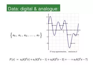
Another look at ADC LSB value This graph shows the fitting of a linear voltage to an ADC in theory. Visible is the quantization error which is the overhang of the digital step higher and/or lower than the ideal value. The ideal quantization error is ± ½ LSB. The LSB is aka Resolution.
Role of ADC module in microcontrollers The ADC module is one of a number of modules on a microcontroller. Others include General Purpose I/O, Comparators, Digital to Analog Converters , Op Amps, Timers, Real-Time clock, AES encryption, Brown-Out Reset, Direct Memory Access, Memory Protection Units, Supply Voltage Supervisors, Capacitive Touch Sense I/O, Communications (UART,SPI, I2C, IrDA, USB, Ethernet), LCD, and other specialty designs.
This is the block diagram for the TI MSP430 Sigma-Delta 16 bit ADC A/D Results Register