Download
1 / 17
260 likes | 499 Vues
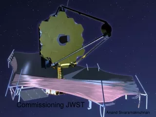
Co-phasing JWST during commissioning using Dispersed Hartmann Sensing or Dispersed Fringe Sensing. Anand Sivaramakrishnan Telescopes Branch, Instrument Division Space Telescope Science Institute methods developed by Paul Atcheson, Scott Acton (Ball), Fang Shi (JPL). From Atcheson (BATC).

E N D
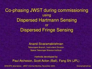
Co-phasing JWST during commissioningusingDispersed Hartmann SensingorDispersed Fringe Sensing Anand Sivaramakrishnan Telescopes Branch, Instrument Division Space Telescope Science Institute methods developed by Paul Atcheson, Scott Acton (Ball), Fang Shi (JPL) DHS/DFS description, JWST Informal Monthly, November 2003 Sivaramakrishnan
From Atcheson (BATC) Commissioning Process – Operational Performance Assumptions PM/SM Deployment • OTE - 0.5 arcsec 1-s pointing • PM segments - <100 mm, 1 arcmin wing deployment • <100 mm ROC, 0.5 arcmin tilt, 100 mm piston • SM - <3 mm linear position, 5 arcmin tilt Control Sense C 1. Coarse Alignment <100 mm seg piston, <200 nm rms WFE >150 mm seg piston, >250 nm rms WFE S Commission 2. Coarse Phasing/ Fine Guiding C Accomplished in transit to L2 (20 days) <1 mm rms WFE, <8 marcsec LOS jitter >1 mm rms WFE range, <10 nm accuracy S C 3. Fine Phasing <100 nm rms WFE setpoint 150 nm rms WFE worst case decay Maintenance >>150 nm rms WFE range, <10 nm measurement accuracy As required (~1 hr weekly or monthly) S 4. Wavefront Monitoring Sensing requirements at each step determine interface parameters – FOV, etc. DHS/DFS description, JWST Informal Monthly, November 2003 Sivaramakrishnan
From Atcheson (BATC) Where does Coarse Phasing fitin JWST commissioning? Before coarse phasing At end of Coarse Alignment < 100 micron segment piston < 200 nm RMS wavefront error (WFE) At end of Coarse Phasing < 1 micron RMS WFE < 8 mas Line of Sight (LOS) jitter After guiding After coarse phasing DHS/DFS description, JWST Informal Monthly, November 2003 Sivaramakrishnan
Actuator Single actuator Gears Large coarse motion Small Fine motion Cryogenic Excellent repeatability DHS/DFS description, JWST Informal Monthly, November 2003 Sivaramakrishnan
Radius of Curvature actuatoron Ball testbed telescope segment(TBT: same basic design as JWST, smaller size) DHS/DFS description, JWST Informal Monthly, November 2003 Sivaramakrishnan
Bipod Actuation Flexures attach actuator to back of segment DHS/DFS description, JWST Informal Monthly, November 2003 Sivaramakrishnan
Single segmenton Ball testbed telescope segment 3 bipods = 1 hexapod RoC actuator in middle (hanging free from back surface) DHS/DFS description, JWST Informal Monthly, November 2003 Sivaramakrishnan
What is Fringe Sensing? Circular aperture Cut it horizontally across a diameter Offset one half by some piston error (a ‘step’ across the cut) What is the PSF at various wavelengths? PSFs for same piston at different wavelengths DHS/DFS description, JWST Informal Monthly, November 2003 Sivaramakrishnan
From Fang Shi (JPL) How is the Fringe Formed? L L x x Segmented Telescope DFS Grism DFS Fringe l Increases Dark Band Dispersion Wavefront Pistoned Piston Corrected Final data strip on detector DHS/DFS description, JWST Informal Monthly, November 2003 Sivaramakrishnan
From Fang Shi (JPL) DFS fringes from Keck tbd tbd Red dots show 12 subaperture locations, each seeing two segments DHS/DFS description, JWST Informal Monthly, November 2003 Sivaramakrishnan
What is DHS? Place a PRISM over the edge between two adjacent segments prism tilts the resulting spot away from ‘on-axis’ location on detector When sent through GRISM the spot is smeared out in l same as a DFS fringe On a different pair of segments use a diffent tilt prism this spot does not overlap the first spot a second DFS-like fringe is created Measure relative piston between all pairs of adjacent segments using a single exposure DHS/DFS description, JWST Informal Monthly, November 2003 Sivaramakrishnan
From Scott Acton (BATC) DHS Simulations -30 –20 –10 –5 0 5 10 20 30 microns • Simulation code allows user to specify: • Center wavelength • Width of light spectrum • Number of discrete wavelengths in the simulation • Percent full well in the images • Read noise • Dark current • Magnitude of star (affects noise due to dark current) • Dispersion in X and Y directions • Image sampling parameters Assume pupil is 35 mm dia. DHS/DFS description, JWST Informal Monthly, November 2003 Sivaramakrishnan
DHS observing sequence - summary 1 sensing, 1 check observation (best case) ~5 worst case • Slew to target • Lock with FGS (on 5x blur) • Take two ~100s NIRCam exposures with two pupil wheel positions • Downlink data, analyze, determine segment updates • Upload actuator commands • Take two ~100s NIRCam exposures with two pupil wheel positions • Adjust all segments • Take two ~100s NIRCam exposures with two pupil wheel positions • Downlink data, analyze --- DONE (with good actuators)! DHS/DFS description, JWST Informal Monthly, November 2003 Sivaramakrishnan
From Fang Shi (JPL) DFS for 18-Hex Example: Segment Group Group #5 15 14 13 Group #4 16 5 4 12 Group #3 11 17 6 3 Group #2 18 2 1 10 Group #1 8 9 7 • Two-grism approach provides optimal visibility for all operations • 2 crossed dispersed grisms in NIRcam filter wheel (may have 1 in each of 2 channels) • 7 images • First phases segments into rows • Then phases rows to each other • Fine phasing between each “big move” to remove residual tilts • Position the groups along a 45º line so that fringes from vertical and horizontal dispersion grism won’t collide • The spots are (from lower left): PARKING LOT, Group #1, #2, #3 (middle), #4 and #5 • Spots are separated by 1 arcsec in x and y in the simulations Tilt test segment pairs (cyan & magenta) away from PARKING LOT PARKING LOT DHS/DFS description, JWST Informal Monthly, November 2003 Sivaramakrishnan
DFS observing block - summary7 or more iterations (best case) ~20 worst case? • Slew to target • Move N segment pairs out of PARKING LOT • Guide w/FGS on some spot? • Take two NIRCam exposures with grisms in pupil wheel • Command segment tilts to re-arrange segment pairs • Take NIRCam exposures • Repeat till all required segment pairs have been observed • Downlink and analyze, prepare segment updates • Repeat 7 times (or more) till measurement meets spec . . . DHS/DFS description, JWST Informal Monthly, November 2003 Sivaramakrishnan
DHS Strengths/weaknesses • Simple FGS operation • Catastrophic pupil misregistration of grism assembly is fatal • Monotonic improvement of PSF with each iteration • Measurement does not require actuation • 5 days to coarse phase if actuators misbehave • Ground verification needs work during I&T • DHS is the baseline approach DHS/DFS description, JWST Informal Monthly, November 2003 Sivaramakrishnan
DFS strength/risks • Strengths • Catastrophic pupil misalignment not an issue • Risks • Non-monotonic image quality during process • Measurement requires actuation • Many more iterations with single grism • 20 days to coarse phase if actuators misbehave (possibly fatal) • DFS is the fallback approach DHS/DFS description, JWST Informal Monthly, November 2003 Sivaramakrishnan