Download
1 / 34
590 likes | 1.31k Vues
Screw Compressor Rotor Training manual. Contents. 1. Part position ... ..………………………………………………… 2 2. Probe setup …………………………………………………… 3 3 . Import nominal profile data……………………………………… 4 4. Create helical vector …………………………………………… 9 5. File structure …………………………………………………… 11

E N D
Screw Compressor Rotor Training manual
Contents 1. Part position ... ..………………………………………………… 2 2. Probe setup …………………………………………………… 3 3. Import nominal profile data……………………………………… 4 4. Create helical vector…………………………………………… 9 5. File structure …………………………………………………… 11 6. Screw compressor rotor‘s function ………………………… 12 7. Define Screw compressor rotor’s data ……………………… 13 8. Create PC-DMIS part program……………………………… 26 9. Execute part program & evaluate dimension ……………… 27 10. Report analysis ……………………………………………… 29
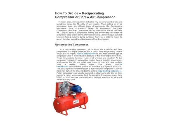
Part position on the CMM Table – Rotation axis of the Screw Compressor= Z axis of the CMM. - Part rotation – any, prefferably use some references, likepicturesbellow Female Male Y Z Z Y X X X X
2. Probe setup Stylus number is configured the same as the number of teeth of the part. Stylus No.1 = -X axis direction (not a must, but a good suggestion – see pictures bellow) Teeth = 5 TIP5 TIP4 TIP1 TIP3 TIP2 Teeth = 4 TIP4 TIP1 TIP3 TIP2 Y Y X X
3. Import nominalprofile data 1) Import nominal profile from a text file. (X,Y Data) X Y Import text file Name of Profile
3. Import nominal profile data 2.1) Import nominal profile from a 3D CAD model After you import the 3D CAD model from PC-DMIS using Linear_Open_Scan, generate an off-line scan to extract nominal profile. Create the scan in CCW direction!
3. Import nominal profile data 2.2) Import nominal profile from a 3D CAD model Start CA and import the nominal profile generated in PC-DMIS.
3. Import nominal profile data 3) Adjust the data Change the Z value of the points to “0”. Check again the point flow – must be CCW!
Female Profile Male Profile
4. Create helical vector ※ In case imported nominal profile from a 3D CAD model, there might beni need of create helical vector. Length of Lead per pitch Helix direction Probe radius compensation (Generally ‘0’) Probe R comp direction
Eventually show the vectors, to ensure yourself, they are created correctly.
5. File structure C:\CurveAnalyzer\Scrcomp\ S/C rotor part data(spec) file PC-DMIS Part program file CurveAnalyzer Measured data file C:\CurveAnalyzer\Scrcomp\”Name of S/C rotor part data”_Saved\ Backup files of CurveAnalyzer Measured data file ※ C/A Measured file name + date & time Backup folder of CurveAnalyzer Measured data files CurveAnalyzerMeasured data files PC-DMIS Part program files S/C rotor part data files
6. Screw compressor rotor’s function . CurveAnalyzer menu Measure -> Screw compressor rotors… Profile view (top face of S/C rotor) Evaluate current measurement Create new part Edit selected part Delete selected part List of Part data files Create copy of the current part Summary view part data Create PC-DMIS Part program Manage backup – recall/delete Execute part program & evaluate Setup measuring and evaluation parameters
7. Define Screw compressor rotor’s data . CurveAnalyzer menu Measure -> Screw compressor rotors… -> New
7. Define Screw compressor rotor’s data 1) Define generally geometry data- Female Part’s ID or Name Select nominal profile Tooth width of S/C rotor (Z axis direction) Length of lead Choose two points of the nominal profile for set the rotate axis
7. Define Screw compressor rotor’s data 1) Define generally geometry data- Male Part’s ID or Name Select nominal profile Tooth width of S/C rotor (Z axis direction) Length of lead Choose two points of the nominal profile for set the rotate axis
7. Define Screw compressor rotor’s data 1) Define generally geometry data– Profile view mode Click right mouse button Section profile view Rotate profile Top face full profile The highlighting is No.1 of profiles Counter clockwise 2,3,4… Adjust the top face of the actual part, as it will be placed on the CMM, and the like, click left mouse button. ※ ㅣ= Lead
7. Define Screw compressor rotor’s data 2) Measurement configuration Safety distance of part around Z axis safety height from top face Probe approach distance for alignment Probe approach distance for measurement Currently probe name & shape
7. Define Screw compressor rotor’s data 2) Measurement configuration– Probe setup If you use a index probe head. Changes in the following format. => T1A90B-90 Name of probe (As in PC-DMIS!) Stylus numbers Direction of No.1 tip Diameter of stylus
7. Define Screw compressor rotor’s data 3) Alignment setup Auto vector point Defined scan Unknown scan Setup alignment location & range Upper diameter Z Position Cylinder height Z Position Cylinder height Lower diameter
7. Define Screw compressor rotor’s data 3) Profile measurement setup- Female All = Full profile measurement 1 = No.1profilemeasurement Profile form tolerance Ref. Is Nominal Ref. Is Measured Auto vector point Defined scan Unknown scan Profile & probe view formeasurement height. Check if OK! Eventually change Z position!
7. Define Screw compressor rotor’s data 3) Profile measurement setup- Male All = Full profile measurement 1 = No.1profilemeasurement Profile form tolerance Ref. Is Nominal Ref. Is Measured Auto vector point Defined scan Unknown scan Profile & probe view of measurement height
7. Define Screw compressor rotor’s data 4) Lead measurement setup- Female All = Full lead measurement 1 = No.1 lead measurement Lead total form tolerance Auto vector point Defined scan Unknown scan Flank 1 Same as the rotate axis points Flank 2 Point number of nominal profile for Flank 1 measurement Lead measurement location view Point number of nominal profile for Flank 2 measurement
7. Define Screw compressor rotor’s data 4) Lead measurement setup- Male All = Full lead measurement 1 = No.1 lead measurement Lead total form tolerance Auto vector point Defined scan Unknown scan Point number of nominal profile for Flank 1 measurement Lead measurement location view Point number of nominal profile for Flank 2 measurement
7. Define Screw compressor rotor’s data 4) Lead measurement setup– Graphic display mode Radial Position Flank 1 Tips Flank 2 Tips Scanning rage view of Flank 1 Adjust scanning range of Flank 1 Default = 0 Scanning rage view of Flank 2 Adjust scanning range of Flank 2 Default = 0
7. Define Screw compressor rotor’s data 5) Pitch measurement setup
8. Create PC-DMIS part program . CurveAnalyzermenu Keep PC-DMIS opened, but with no PP opened. Then : Measure -> Screw compressor rotors… -> Generate PC-DMIS PP ※ Before click PC-DMIS PP button Executed PC-DMIS.
9. Execute part program & evaluate dimension . CurveAnalyzermenu Measure -> Screw compressor rotors… -> Measure & Evaluate Part information & comment
9. Execute part program & evaluate dimension . PreAlignment– Manual measuring 1. Top face, 3point probing. (use Tip1) 2. Outer diameter of top face, 3point probing. (use Tip1) ※ In the case of first-run part program, set slow speed of Jogbox.
10. Report analysis Female – IndividualProfile & Lead Error Profile evaluate location Profile form error Lead length error Lead slope error Lead evaluate location Lead form error Lead total form error
10. Report analysis . Female – FullProfile , Lead , Pitch Error Profile form error RUNOUT of Ext dia RUNOUT of Intdia Total form error of full leads Average lead length of totalFlank1 Total form error of a lead IndividualPitch error CummulativePitch error AdjacentPitch error
10. Report analysis . Female – FullProfile Error Profile Total form error Profile - dir form error Profile + dir form error Profile + dir out of tolerance Profile - dir out of tolerance RUNOUT of Ext dia RUNOUT of Intdia
10. Report analysis . Female – FullLead Error Lead total form error Lead form error Lead slope error Lead length error
10. Report analysis . Male - Report