ATM (Asynchronous Transfer Mode)
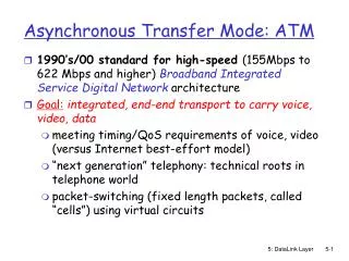
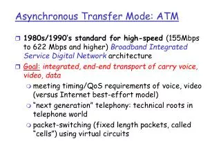
The Asynchronous Transfer Mode (ATM) is a high-speed networking protocol designed for efficient data transmission over optical fiber. Developed by the ATM Forum and adopted by ITU-T, ATM serves as a connection-oriented system that prioritizes reliable delivery of diverse data types, including voice and video. It handles multiplexing of different packet sizes through fixed-size cells, ensuring predictable data exchange with minimal delay. The architecture includes components like transmission paths, virtual paths, and virtual circuits that facilitate seamless integration with existing telecommunications systems.

ATM (Asynchronous Transfer Mode)
E N D
Presentation Transcript
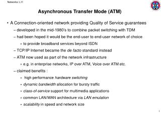
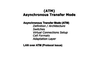
ATM (Asynchronous Transfer Mode) Cell Relay protocol designed by the ATM Forum and adopted by the ITU-T
To optimize the use of high-data-rate transmission media (Optical fiber) Need for a system that can interface with existing systems Need for a design that can be implemented inexpensively so that cost would not be a barrier to adoption The system must be able to work with and support the existing telecommunications hierarchies (local loops, local providers, long distance carriers and so on) The system must be connection-oriented to ensure accurate and predictable delivery. T move as many of the functions to hardware as possible. Design Goals & Challenges
Multiplexing Using Different Packet Sizes X – data packet A, B, C - audio or video packet
ATM Multiplexing Cell networking Cell – a small data unit of fixed size Cell network uses the cell as the basic unit of data exchange Advantage Predictability & uniformity – less delay Interleaving – makes it possible to handle real-time transmissions
TP, VPs, and VCs Transmission path – physical connection (wire, cable, satellite) between an end point & a switch or between switches, divided into several VPs (set of all highways that directly connects two cities) Virtual path – provides a connection or set of connections between two switches. (highway) Virtual circuits – logically connects two points together, source and destination (lanes of a highway.)
Connection Identifiers Virtual connection is defined by a pair of numbers : the VPI and the VCI
Virtual Connection Identifiers in UNIs and NNIs
2 Types of Connection 1. PVC- like a leased line 2. SVC Setup shown at the figure The actual mechanism depends on the network layer
VP switch – route the cell using only the VPI most of the switches in a typical network VPC – routes the cell using VPIs & VCIs Allows hierarchical routing Switches at the boundaries of the network, those that interact directly with the end point devices Two Types of Switches
Crossbar switch Knockout switch Banyan switch Batcher banyan switch Switch Fabrics
Part I Example of Routing in a Banyan Switch (a)
Part II Example of Routing in a Banyan Switch (b)
ATM Layers in End-Point Devices and Switches
AAL1 supports applications that transfer information at constant bit rates such as video & voice Allows ATM to connect existing digital telephone networks such as DS-3 or E-1 Applications: real time voice and video AAL2 Intended to support variable bit-rate applications Applications: compressed voice, video, or data AAL3/4 AAL3 – intended to support connection-oriented data services AAL4 – intended to support connectioness services Applications: X.25 & TCP/IP AAL5 Simple and efficient adaptation layer (SEAL) Assumes that all cells belonging to a single message travel sequentially Applications: point-to-point internetwork transmissions AAL Types
AAL1 CSI – for signaling purposes – not yet clearly defined
AAL2 SAR – 45 bytes Header – 1 byte - 1 bit – CSI CS identifier - 3 bits – SC sequence count – modulo 8, for ordering and end-to-end flow and error control - 4 bits – ITinformation type – identify the data segment as falling at the beginning , middle or end of the message Trailer – 2 bytes - 6 bits – LI length indicator – used with the final segment of a message (to know the length of data in the final cell – how mush is data, how much is padding) - 10 bits – CRC – for the entire data unit
Note: each field added in CS is in byte T – 0 BT – for sync, & identifies the first cell BA – tells the receiver how much buffer size is needed for the coming data AL – to make the rest of the trailer 4 bytes long ET – for sync L – indicates the length of the data unit Header & Trailer at CS
ST (segment type) beginning, middle, end of message or single-segment message SC (sequence count) for end-to-end error and flow control MID (mux id) Identifies cells coming from different data, flows & multiplexed on the same virtual connection LI (length indicator) used with the final segment of a message, identified by ST (to know the length of data in the final cell – how mush is data, how much is padding) Header & Trailer at SAR
AAL5 UU – left to the discretion of the user T – reserved but not yet defined L – how much of the message is data, how much is padding
ATM Layer ATM layer provides routing, traffic management, switching and multiplexing services
ATM Header CLP – for congestion control
Service Classes Constant bit rate – real time audio& video services Variable bit rate ( real time & nonreal time) – audio & video that use compression technique Available bit rate – bursty data, delivers cell at a minimum rate Unspecified bit rate – does not guarantee anything
Service Classes and Capacity of Network of the network
Sustained cell rate (SCR) Average cell rate over a long time interval Peak Cell rate (PCR) Sender’s maximum cell rate Minimum Cell Rate Minimum cell rate acceptable to the sender Cell variation delay tolerance (CVDT) Measure of the variation in cell transmission times Ex. CVDT = 5ns, it means that the difference between the min & max delays in delivering the cells should not exceed 5ns User Related Attributes
Cell loss ratio (CLR) Fraction of cells lost Cell transfer delay (CTD) Average time needed for a cell to travel from source to destination Cell delay variation (CDV) Difference between the CTD max and CTD min Cell error ratio (CER) Fraction of cells delivered in ratio Network Related Attributes
ATM WAN Routers with 2 stacks of protocol