Download
1 / 13
130 likes | 331 Vues
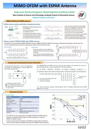
New preamble structure for AGC in a MIMO-OFDM system. Tsuguhide Aoki, Daisuke Takeda, Takahiro Kobayashi and Kazuaki Kawabata Corporate R&D center, TOSHIBA corporation tsuguhide.aoki@toshiba.co.jp. Main scope of TGn. “Achieve 100Mbps measured at MAC SAP” (PAR & FR)

E N D
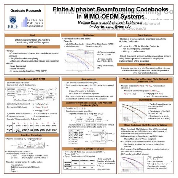
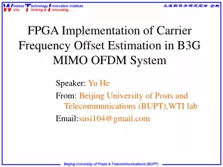
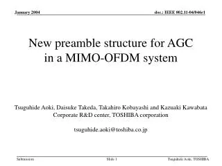
New preamble structure for AGC in a MIMO-OFDM system Tsuguhide Aoki, Daisuke Takeda, Takahiro Kobayashi and Kazuaki Kawabata Corporate R&D center, TOSHIBA corporation tsuguhide.aoki@toshiba.co.jp Tsuguhide Aoki, TOSHIBA
Main scope of TGn • “Achieve 100Mbps measured at MAC SAP” (PAR & FR) ⇒MIMO-OFDM is one of the possible candidates. • “Some of the modes shall be backwards compatible and interoperable with 802.11a and/or 802.11g”(PAR & FR) • Backward compatibility between legacy 11a and MIMO-OFDMis one of the main issues. • Preamble structure of 11a should be maintained in a MIMO-OFDM system. Alternatively, use protection mechanisms as defined in 11g (RTS-CTS, CTS self) Tsuguhide Aoki, TOSHIBA
GI LP LP GI GI LP -LP Example of preamble structure for MIMO system Same as 11a →Backward compatibility Channel estimation for MIMO signals • AGC for Tx1 could be performed by using the legacy SP. • It is difficult to adjust the gain control for Tx2-Tx4 during MIMO signals because of the insufficient information for other antennas. →This causes a severe saturation or quantization error in ADC. TX1 DATA GI LP GI LP GI LP GI LP SP Sig Sig 2 TX2 GI LP GI LP GI -LP DATA GI -LP TX3 GI LP GI -LP GI -LP GI LP DATA Indicate 11n preamble structure TX4 GI LP GI -LP DATA *Similar structure is presented in 03/714r0 Tsuguhide Aoki, TOSHIBA
GI LP LP New preamble structure with 2nd SPs for MIMO system 1st AGC 2nd AGC • The 1st AGC for Tx 1 could be performed by using legacy SP. • The 2nd AGC for MIMO signals could be performed by using the 2nd SPs. • The 2nd SP with same sequence for Tx1-Tx4 causes a Null (beamforming) effect. -->Different sequence should be used for the 2nd SP on each antenna. TX1 DATA GI LP GI LP SP Sig GI LP Sig2 2nd SP GI LP TX2 GI LP GI LP GI -LP 2nd SP GI -LP DATA TX3 2nd SP GI LP GI -LP GI -LP GI LP DATA TX4 2nd SP DATA GI LP GI -LP GI LP GI -LP 2nd SP for MIMO-AGC Tsuguhide Aoki, TOSHIBA
Simulated transmit signals with 2nd SP MIMO DATA MIMO LP LP SIG1&2 2nd SP SP Total transmission power is always the same. ・・・ f Tx 1* ・・・ f Tx 2 ・・・ Tx 3 f ・・・ f Tx 4 Base-band transmit signals (In-phase) *Tx 1 transmits same sequence of legacy SP. Tsuguhide Aoki, TOSHIBA
Simulated receive signals with 2nd SP Target gain for the selected antenna is used for all RF/IF chains. Select an antenna with maximum power. 2nd SP 1st SP Rx 1 Rx 2 Rx 3 Rx 4 2nd AGC 1st AGC Base-band transmit signals (In-phase) Tsuguhide Aoki, TOSHIBA
Normalized received power for data Normalized received power of 2nd SP (new preamble) Distribution of the received power for data part and 1st /2nd SP part in channel model C(NLOS) 3 by 3 MIMO-system Normalized received power for data Saturation Quantization error Normalized received power of SP (conventional preamble) This figure shows the power of antenna with maximum power in SP(2nd SP) Tsuguhide Aoki, TOSHIBA
Simulation parameters Tsuguhide Aoki, TOSHIBA
BER/PER performance vs. average amplitude of SP in channel model B(NLOS) PSDU=1000bytes for each,10bit-ADC Tsuguhide Aoki, TOSHIBA
BER/PER performance vs. average amplitude of SP in channel model C(NLOS) PSDU=1000bytes for each,10bit-ADC Tsuguhide Aoki, TOSHIBA
BER/PER performance vs. average amplitude of SP in channel model D(NLOS) PSDU=1000bytes for each,10bit-ADC Tsuguhide Aoki, TOSHIBA
BER/PER performance vs. average amplitude of SP in channel model E(NLOS) PSDU=1000bytes for each,10bit-ADC Tsuguhide Aoki, TOSHIBA
Conclusions • A new preamble structure with 2nd SP has been examined. • The new SP is less demanding on the dynamic range of the AGC. • For a given AGC dynamic range, BER /PER performance is improved. Tsuguhide Aoki, TOSHIBA