Download

1 / 37
370 likes | 538 Vues
Improved Functional Magnetic Resonance Imaging at 4.0 T. Kimberly Brewer PhD External Defence – Physics and Atmospheric Science March 18, 2010. MRI and Relaxation. B 0. z ’. z ’. z ’. 90 o. R 2 - transverse signal decay rate due to spin-spin interactions (R 2 = 1/T 2 )

E N D
Improved Functional Magnetic Resonance Imaging at 4.0 T Kimberly Brewer PhD External Defence – Physics and Atmospheric Science March 18, 2010
MRI and Relaxation B0 z’ z’ z’ 90o • R2 - transverse signal decay rate due to spin-spin interactions (R2 = 1/T2) • R2’ - transverse relaxation rate from local field inhomogeneities (R2’ = 1/T2’) • R2* = R2 + R2’ M M y’ y’ y’ x’ x’ x’
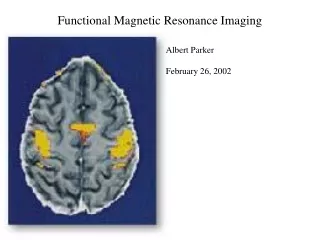
Functional MRI (FMRI) - BOLD • BOLD – Blood oxygen level-dependent • DeoxyHb is paramagnetic, oxy Hb is diamagnetic • More deoxyHb the MRI signal • After stimulus, ratio of oxy Hb/deoxyHb, causing in the MRI signal • A R2*-weighted sequence is generally used for fMRI • At high fields, BOLD CNR increases
Susceptibility Field Gradients (SFGs) • Occur in regions where the magnetic susceptibility changes rapidly • E.g. Inferior temporal, orbital frontal • The large magnetic field gradients cause rapid dephasing • Causes signal loss and other artifacts • No fMRI activation in these regions, or activation is displaced • Effects are worse at higher magnetic fields Traditional “Ideal”
K-Space and Images • Signal collected as frequency and phase information – build representation of image in k-space • Image is complex – has both magnitude and phase information • K-space traversal depends on gradient patterns • Use rectilinear or spiral trajectories FT
Spiral-In vs Spiral-Out TE Spiral-In TE = 30 ms Spiral-Out TE = 19 ms 1. Glover and Law, Magn Reson Med46:515-522 (2001)
“Ideal” Sequence for SFG regions • Minimal apparent geometric distortion • Maximum signal-to-noise ratio (SNR) • Optimal R2’-weighting for maximum BOLD contrast-to-noise ratio (CNR) • High specificity to extravascular sources (less sensitivity to large vessels)
Asymmetric Spin-Echo (ASE) Spiral TE TE* TE* TE*
Asymmetric Spin-Echo (ASE) Spiral Spiral-Out ASE Image 1 ASE Image 2
SNR Results 8 subjects
fMRI Results Spiral-Out ASE Image 1 ASE Image 2 ASE Image 3 30s breath-holding task, 5 subjects
ASE Spiral & Specificity • Spin-echo more specific to tissue compared to vessel at high magnetic field strengths • The T2 of blood at high fields is quite short • At TE > 65 ms (4 T), less than 25% of spin-echo fMRI signal is intravascular • Increasing R2-weighting in later ASE spiral images may lead to specificity improvements • Common TE/TE* combinations (ie. 60-70/30 ms) - third ASE image has effective R2-weighting = a spin-echo spiral-in at TE = 90-100 ms. • Determine where ASE spiral activation is located • Compare to pure gradient-echo and spin-echo
FMRI Results 20s alternating checkerboard task, 12 subjects, 2mm in-plane resolution, 3mm thick
Average % Signal Change (ΔS/S) in Tissue and Vasculature 20s alternating checkerboard task task, 12 subjects
Sensitivity vs Specificity • Later ASE images similar to spin-echo images • In appearance and in % signal change • Have not yet proved that later images are more specific • Need a better metric – Use an individualized specificity analysis with venogram • Based off ROC curves - function of false positive rate (FPR) • Number of false positives – activation on veins; Number of true negatives – voxels in vessels with no activation) • specificity = 1 – FPR • Generate specificity curves as a function of varying z-thresholds – the faster a curve reaches a value of 1.0, the more specific it is to tissue compared to vessel
FPR = 50% FPR = 0% 12 subjects
Conclusions - Specificity • The 2nd ASE image may be the most useful • Has stronger activation (and more active voxels) • The specificity curve is not significantly different than the 3rd image • Could help improve temporal resolution • May be able to change TE/TE* to improve intravascular suppression
Conclusions • Developed a novel pulse sequence, ASE spiral, that is effective at recovering signal lost in SFG regions while maintaining significant BOLD contrast • Determined that individual ASE spiral images have varying degrees of sensitivity and specificity to fMRI activation • The 2nd and 3rd ASE images are more specific to extravascular sources than either spiral-in or spiral-out
Acknowlegements • Dr. Steven Beyea • Dr. Chris Bowen • Dr. Ryan D’Arcy • Careesa Liu • SujoyGhosh-Hajra • Dr. MartynKlassen • Janet Marshall • James Rioux • Lindsay Cherpak • Tynan Stevens • Jodie Gawryluk • Erin Mazerolle • Connie Adsett • Ahmed Elkady • Everyone at IBD Atlantic… Walter C. Sumner Foundation
Future Directions – Current Impact • ASE spiral is currently being used to study white matter fMRI • Collaborators have found that ASE spiral is more sensitive to the detection of activation located in white matter (corpus callosum) • Increase from 21% to 100% of subjects with activation • Also saw increasing ΔS/S with increasing R2-weighting • ASE spiral is currently being used for a temporal lobe epilepsy study • Has successfully elicited activation throughout the temporal cortex in several subjects and is insensitive to signal loss around metal clips found in post-surgical patients
Future Directions • Further spiral-in/spiral-out simulations • Using a realistic head model will give more accurate signal displacement information • Comprehensive study is currently be doing to compare ASE spiral and other SFG recovery methods (spiral-in/out & spiral-in/in) to traditional (EPI & spiral) and non-BOLD (spin-echo spiral-in/out and FAIR) fMRI techniques • Uses a task to elicit activation in the temporal lobe • Will determine the effectiveness of signal recovery using a cognitive task • Monte Carlo simulations would be useful for modeling the specific contributions (tissue vs vasculature) occurring in both grey and white matter for each of the individual ASE spiral images • Also need to investigate different image addition methods • May be able to gain both specificity and sensitivity benefits in post-processing
Conclusions - Specificity • Later ASE spiral images have activation patterns similar to spin-echo images • ΔS/S increases with increasing R2-weighting in tissue but remains constant in vasculature • The 2nd and 3rd ASE spiral images are more specific than a pure gradient-echo, but less specific than spin-echo • The 2nd ASE image may be the most useful • Has stronger activation (and more active voxels) • The specificity curve is not significantly different than the 3rd image • Could help improve temporal resolution • May be able to change TE/TE* to improve intravascular suppression
Conclusions – ASE spiral • Each individual image has reduced apparent geometric distortion and minimal signal loss • SNR decreases with increasing R2-weighting & % signal change increases to compensate • Each image has equivalent CNR • Combining images gives higher SNR and has more active voxels
ASE Spiral vs Spiral-Out • 8 healthy adults (4 males, 4 females) • 30 s breath-holding task • 3 subjects were excluded from fMRI results • TR = 3 s, 13 slice (5 mm, gap 0.5 mm) • 64 x 64 (240 x 240 mm) resolution • Spiral-out: TE = 25 ms • ASE spiral: TE* = 25 ms, TE = 70 ms • Multiple images were combined with equal weighting
Z-shim Asymmetric Spin-Echo Spiral • Can use unique z-shim gradient (in red) for each individual ASE image
Z-Shim Automated Routines • Prescan-based routines – Optimal combination must have sufficient SNR and large number of recovered voxels • MIP-based routine - Images are combined with a maximum intensity projection (MIP) in routine • SS-based routine – Images are combined with a sum-of-squares (SS) in routine • B0 field routine – Developed by Truong and Song (2008) • Calculates offsets from an initial field map and calculates the gradients necessary to provide opposing phase twist * Truong et al., MagnReson Med59:221-227 (2008)
Z-Shim ASE Spiral vs ASE Spiral • 8 healthy adults (4 males, 4 females) • 24 s breath-holding task • 1 subject was excluded from fMRI results • TR = 4 s, 18 slice (5 mm, gap 0.5 mm) • 64 x 64 (240 x 240 mm) resolution • Z-shim ASE spiral & ASE spiral: TE* = 25 ms, TE = 70 ms • Images were combined with MIP or SS
ASE Spiral Specificity Experiment • 12 healthy adults (3 males, 9 females) • 20 s alternating checkerboard task • Alternating at 8 Hz • TR = 2 s (4-shot), 4 slices (3 mm, gap 0.5 mm) • Slices centred and aligned along calcarinesulcus • 128 x 128 (240 x 240 mm) – 1 mm in-plane resolution • Spiral-in/out: TE = 30 ms • Spin-echo spiral-in/out: TE = 105 ms • ASE spiral: TE* = 30 ms, TE = 75 ms • Venogram: 256 x 256, TE = 30 ms – used for delineation of vessels
ASE Spiral Specificity Experiment • 12 healthy adults (3 males, 9 females) • 20 s alternating checkerboard task • Alternating at 8 Hz • 4 slices (3 mm) • Slices centred and aligned along calcarinesulcus • 2 mm in-plane resolution • Sequences: Spiral-in/out, spin-echo spiral-in/out, ASE spiral • Venogram (1mm in-plane resolution) – used for delineation of vessels