Download
1 / 37
370 likes | 529 Vues
From the conference poster. Poster shows compilation of results of PMT R&D for Focusing DIRC. New Results on Focusing DIRC. Outline: • DIRC Concept • BABAR-DIRC Performance • R&D for Focusing DIRC – Prototype Design – Photodetector Selection – Performance in Beam Test.

E N D
From the conference poster Poster shows compilation of results of PMT R&D for Focusing DIRC New Results on Focusing DIRC Outline: • DIRC Concept • BABAR-DIRC Performance • R&D for Focusing DIRC – Prototype Design – Photodetector Selection – Performance in Beam Test Jochen Schwiening for the Focusing DIRC group at SLAC
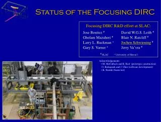
DIRC Concept Detection of Internally Reflected Cherenkov Light Novel Ring Imaging CHerenkov detector § based on total internal reflection of Cherenkov light used for the first time in BABAR for hadronic particle identification Recent improvements in photon detectors have motivated R&D efforts to improve the successful BABAR-DIRC and make DIRCs interesting for future experiments (Super B-Factory, Panda, GlueX, ILC) Focusing DIRC R&D group at SLAC: • Ivan Bědajánek • Jonathon Coleman • Gholam Mazaheri • Jochen Schwiening • Jaroslav Va’vra • Jose Benitez • David W.G.S. Leith • Blair N. Ratcliff • Josef Uher • Acknowledgements: • M. McCulloch and B. Reif (prototype construction) • M. Barnyakov, M. Ji, S. Kononov, and K. Suzuki (beam test) §B.N. Ratcliff, SLAC-PUB-6047 (Jan. 1993)
DIRC Designs BABAR-DIRCoperating since 1999 3D imaging a) x-coordinate b) y-coordinate c) time (≈1.7ns)PID primarily from x&y coordinates TOP counter (Nagoya)proposed for BELLE2D imaging a) x-coordinate b) time ( < 100ps)PID from x&time coordinates Focusing DIRC prototype (SLAC): 3D imaging a) x-coordinate b) y-coordinate c) time ( < 130ps)PID from all three coordinates
Focusing DIRC R&D Roadmap • Work with manufacturers to develop and characterize one or more fast, pixelated photon detectors including; • basic issues such as cross talk, tube lifetime, and absolute efficiency • operation in 15 kG field • Measure timing resolution, uniformity, and cross talk in lab using fast laser system • Measure single photon Cherenkov angular resolution in a test beam • use a prototype with a small expansion region and mirror focusing, instrumented with a number of candidate pixelated photon detectors and fast (25 ps) timing electronics. • use 3D imaging (x&y coordinate and time) over-constraint very useful to deal with backgrounds and to develop corrections • demonstrate performance parameters • demonstrate correction of chromatic production term via precise timing • measure N0 and timing performance of candidate detectors. All Focusing DIRC results shown today are preliminary. See also poster #222 “Progress on the Focusing DIRC R&D” J. Benitez et al.
BABAR-DIRC Principle • Charged particle traversing a radiator with refractive index n withb = v/c> 1/nemits Cherenkov photons on cone with half opening angle cos qc = 1/bn(l). • If n>2 some photons are always totally internally reflected for b1 tracks. • Radiator and light guide: Long, rectangular Synthetic Fused Silica (“Quartz”) bars (Spectrosil: average <n(l)> 1.473, radiation hard, homogenous, low chromatic dispersion) • Photons exit via wedge into expansion region (filled with 6m3 pure, de-ionized water). • Pinhole imaging on PMT array(bar dimension small compared to standoff distance).(10,752 traditional PMTs ETL 9125, immersed in water, surrounded by hexagonal “light-catcher”,transit time spread ~1.5nsec, ~30mm diameter) • BABAR-DIRC is a 3-D device, measuring: x, y and time of Cherenkov photons,defining qc, fc,tpropagationof photon. (time measurement used primarily for rejecting accelerator background and resolving ambiguities)
BABAR-DIRC Operational Experience Over six years of experience in PEP-II/BABAR B-factory mode §: DIRC is reliable, robust, easy to operate • DIRC reached performance close to design within first year of running. • DIRC plays significant role in almost all BABAR physics analyses. • Calibration constants stable to typically rms < 0.1ns per year. • 98% of channels fully functional after 7+ years immersed in ultra-pure water. • No problems with water or gas systems. • Most significant operational issue: sensitivity to accelerator induced background interacting in the water of the Standoff Box (primarily a DAQ issue)→ Added additional shielding; upgraded TDCs in 2002.→ Time measurement essential in dealing with backgrounds. §Nucl. Instrum. Meth. A502 (2003) 67
BABAR-DIRC Resolution Single Photon resolution s(Dtg) = 1.7 nsec s(Dqc,g) = 9.6 mrad Dqc,g:difference measured qc,g per photon and expected track qc (di-muons) Dtg: difference between measured and expected photon arrival time Nucl. Instrum. Meth. A502 (2003) 67
BABAR-DIRC PID Performance p/K separation power: Measure Cherenkov angle resolution as function of track momentum for pions and kaons, kinematically identified in D decays (D– D0p–, D0 K– p+). about 4.3s separation at 3GeV/c, close to 3s separation at 4GeV/c Nucl. Instrum. Meth. A502 (2003) 67
BABAR-DIRC Performance 4mrad @ 5GeV/c Typical PMT hit rates: 200kHz/PMT (few-MeV photons from accelerator interacting in water) Timing resolution: 1.7nsper photon (dominated by transit time spread of ETL 9125 PMT) Photon yield: 18-60 photoelectrons per track(depending on track polar angle) Cherenkov angle resolution: 9.6mrad per photon → 2.4mrad per track • Focusing DIRC • → Improve single photon timing and angular resolution, decrease size of Cherenkov ring expansion region
Chromatic Effects in DIRC DIRC detector bandwidth Defined by choice of photodetector, glue, medium in expansion region, and loss during photon propagation. Optimization: smaller bandwidth → fewer signal photons, smaller chromatic error Typical DIRC bandwidth: l=300…650nm, <l>=410nm Chromatic effect at Cherenkov photon production Cherenkov photons produced according to cos qc(l) = 1/bn(l) n(l): refractive (phase) index n(l)=1.49…1.46 qc(l): opening angle of Cherenkov cone qc(l,=1)=835…815mrad Chromatic time dispersion during photon propagation Photons propagate in dispersive medium with group index ng(l) time-of-propagation = path-in-bar · ng(l)/c0 ng(l): group index ng(l)=1.57…1.47 Red photons propagate faster than blue photons
Photodetector Selection • Main criteria for selection • Timing resolution • timing resolution σt < 200ps required for chromatic correction • Pixel size • small pixels allow reduction of size of expansion region without compromising angular resolution • Single photon efficiency need quantum efficiency ~20-30% and >70% packing efficiency to match BABAR-DIRC photon yield • Main candidates • Burle 85011-501 MCP-PMT • Burle 85011-430 MCP-PMT • Burle 85021-600 MCP-PMT • Hamamatsu H-8500 Multianode PMT • Hamamatsu H-9500 Multianode PMT • Measure timing resolution, uniformity, and cross talk • PiLas laser diodes (35ps FWHM, l = 407 / 635 nm) • Scan PiLas across PMT face using motion-controlled x&y stage (typical step size 200-500μm) Compilation of 25 scansdifferent PMTs and wavelengths
Burle 85011-501 • Burle 85011-501 MCP-PMT • 64 pixels (8×8), 6.5mm pitch • bialkali photocathode • 25μm pore MCP, 6mm MCP-cathode distance • gain ~5×10⁵ • timing resolution ~70ps, distribution has tail • good uniformity Efficiency relative to Photonis PMT → IEEE NSS 2003 scan: 500mm%1mm, 407nm
Hamamatsu H-8500 • Hamamatsu H-8500 Flat Panel Multianode PMT • 64 pixels (8×8), 6.1mm pitch • bialkali photocathode • 12 stage metal channel dynode • gain ~106 • timing resolution ~140ps Efficiency relative to Photonis PMT → IEEE NSS 2003 scan: 500mm%1mm, 407nm
Detector Optics • Radiator • use 3.7m-long bar made from three spare high-quality BABAR-DIRC bars • use same glue as BABAR-DIRC (Epotek 301-2), wavelength cut-off at 300nm • Expansion region • use smaller stand-off distance (25% of BABAR-DIRC) • coupled to radiator bar with small fused silica block(RTV SES-403) • filled with mineral oil (KamLand experiment) to match fused silica refractive index • include optical fiber for electronics calibration • would ultimately like to used solid fused silica block • Focusing optics • spherical mirror from SLD-CRID detector (focal length 49.2cm) • Photon detector • use array of flat panel PMTs focal plane • readout to CAMAC/VME electronics
Prototype Readout • For 2005 beam tests read out two Hamamatsu H-8500 MaPMTs and three Burle 85011-501 MCP-PMTs (total of 320 pixels) • Elantec 2075EL amplifier (130x) on detector backplane • SLAC-built constant fraction discriminator • Ten Phillips7186 TDCs (25ps/count) for 160 channels • Four SLAC-built TDC boards: TAC & 12 bit ADC (~31ps/count) for 128 channels • Read out only pixels close to expected hit pattern of Cherenkov photons(155 pixels used in analysis shown today) • Calibration with PiLas laser diode (~35ps FWHM) to determine and monitor TDC channel delays and ps/count calibration Photodetector coverage in focal plane Reconstruction: nice aspect of DIRC: geometry plus simple optics defines many photon properties → Pixel with hit (xdet, ydet, thit) defines 3D photon propagation vector in bar and Cherenkov photon properties (assuming90° track, =1,<λ>=410nm)x, y, cos cos cos Lpath, nbounces,c, fc , tpropagation
Beam Test Setup Expansion region Mirror • Prototype located in beam line in End Station A at SLAC • Accelerator delivers 10 GeV/c electron beam(e–) • Beam enters bar at 90º angle. • 10 Hz pulse rate, approx. 0.1 particle per pulse • Bar contained in aluminum support structure • Beam enters through thin aluminum foil windows • Bar can be moved along long bar axis to measure photon propagation time for various track positions • Trigger signal provided by accelerator • Fiber hodoscope (16+16 channels, 2mm pitch) measures 2D beam position and track multiplicity • Cherenkov counter and scintillator measure event time • Lead glass calorimeter selects single electrons • All beam detectors read out via CAMAC (LeCroy ADCs and TDCs, Phillips TDC, 57 channels in total) PMTs scintillator electrons hodoscope double-quartz counter lead glass calorimeter quartz bar
Beam Test Data Expansion region Mirror • In July, August, and November 2005 we took beam data during five periods, lasting from few hours to several days. • Total of 4.1M triggers recorded, 10 GeV/c e– • Reconstructed ~200k good single-track events • Beam entered the radiator bar in 7 different locations. • Recorded between 100k and 700k triggers in each beam location. • Photon path length range: 0.75m–11m. • Simulated full detector with all efficiencies in Geant4. Geant4 Geant4
Beam Detectors Lead glass: single track ADC distribution • Event selection: • require single track signal in hodoscope • require charge in lead glass to be consistent with single electron • require start counter TDC signal in expected time window • Data corrections: • use hodoscope beam spot to correct the path of photons in bar • use ADC measurement in start counters to correct TDC value for time walk→ resulting start counter resolution ~35ps • use PiLas laser diode to calibrate prototype TDCs and cable delays→ all pixels aligned in time e – π– doubles Charge (ADC counts) Start counters: corrected event time σ≈ 35ps Corrected time (ps)
Occupancy and Cherenkov Angle Occupancy for accepted events in one run, 400k triggers, 28k events • Cherenkov angle for all pixels with signal • Have to assign angles to pads assuming that photons hit center of pad (single photons,no center-of-gravity interpolation possible) • clear pixelization effect visible, θc resolution ≈ 14-16mrad (total pixel size ≈ 21mrad inθc space) • θc resolution from pixels worse than expected, should improve with better alignment (plus systematic checks of hardware, calibration, and software) Preliminary position 1 <path> ≈ 9.7m σ= 15.0±2.0mrad thetaC from pixels (mrad)
Time Measurement PiLas calibration of 10 Phillips 7186 TDCs • Precise timing at 50ps level requires • careful calibration of TDC conversion factor Phillips 7186: nominal 25ps/count, varies across measurement range • monitoring of electronics delays to correctly align pixels in time space temperature variations in hall matter • use accelerator trigger signal as event time and monitor event time using start counter (35ps resolution) • correction for charge-sharing and cross talk • Challenging task, PiLas calibration system very important • Results shown today do not have final calibrations and delays yet Data sheet Position 1 direct Position 1 mirror reflection Position 6 Position 6 Mirror hit time (ns)
Chromatic Broadening Mirror → IEEE NSS 2005 • Example for one selected detector pixel in position 1 • First peak ~81cm photon path length • Second peak ~930cm photon path length • Measure time of propagation (TOP) • Calculate expected TOP assuming average <λ>≈410nm • Plot ΔTOP: measured minus expected time of propagation • Fit to double-Gaussian • Observe clear broadening of timing peak for mirror-reflected photons 81cm path σnarrow≈140ps peak 1 ΔTOP (ns) 930cmpath σnarrow≈410ps peak 2 ΔTOP (ns)
Cherenkov Angle from Time Preliminary σnarrow= 7.5±1.0mrad • Cherenkov angle from time of propagation (TOP) • Use measured TOP for each pixel • Combine with calculated photon path in radiator bar • Calculate group index ng(l) fromng(l)= c0· TOP / path • Calculate refractive (phase) index n(l) from group index • Calculate photon Cherenkov angle θc for b=1 qc(l) = cos–1(1/n(l)) • Resolution of θc from TOP is 6-7mrad for photon path length above ~4m. • Expected to improve with better calibration. position 5 <path> ≈ 3.8m Preliminary σnarrow= 6.6±1.0mrad position 1 <path> ≈ 9.7m thetaC from TOP (mrad)
Cherenkov Angle Resolution • Summary of preliminary results • θc resolution from pixels is 14-16mrad for entire range. • θc resolution from time of propagation improves rapidly with path length, reaches plateau at 6-7mrad after approx. 4m photon path in bar. • Next steps: complete calibration and systematic checks, attempt correction of chromatic production term. Preliminary θc resolution ♦ from pixels ■ from time
Plan for Future Prototype Tests • Next beam test of prototype is planned for summer 2006 • plan to add new photon detectors: • new 1024 pixel Burle MCP-PMT • new 256 pixel Hamamatsu Multianode PMT • new small cathode-to-MCP gap 64 pixel Burle MCP-PMT • 256/1024 pixel PMTs will have modified readout combining pixels into 4×16 pseudo-pixels, 64 channels→ provide finer segmentation in vertical direction → minimize pixelization effects, provide betterθc resolution from pixels for chromatic correction. • possibly add a second fiber hodoscope behind prototype to reject tracks with large scattering angle in bar Photo of new 1024 pixel Burle 85021-600 MCP-PMT
Burle 85011-430 • Burle 85011-430 MCP-PMT • 64 pixels (8×8), 6.5mm pitch • bialkali photocathode • 25μm pore MCP, small 0.75mm MCP-cathode distance • gain ~5×10⁵ • timing resolution ~90ps, much smaller tail • OK uniformity Efficiency relative to Photonis PMT → IEEE NSS 2004 scan: 200mm%1mm, 407nm
Hamamatsu H-9500 • Hamamatsu H-9500 Flat Panel Multianode PMT • bialkali photocathode • 12 stage metal channel dynode • gain ~106 • typical timing resolution ~220ps • 256 pixels (16×16), 3 mm pitch • custom readout board – read out as 4×16 channels Efficiency relative to Photonis PMT σnarrow ≈220ps time (ns) scan: 250mm%250mm, 407nm
Summary • Six years of experience in PEP-II/BABAR B-factory mode: DIRC successful, very reliable, robust, easy to operate, plays significant role in almost all BABAR physics analyses. • Focusing DIRC R&D has identified several PMT candidates capable of delivering timing resolution of <140ps with good uniformity and efficiency. Remaining questions include: behavior in magnetic fields, aging, rate capability. • Focusing DIRC prototype is a challenging detector, requiring new approaches to calibration, monitoring, software design, etc. • 3D readout makes system more complex but also more robust, helps with backgrounds and calibrations. Redundancy makes correction of chromatic production error possible. • Test beam data for prototype show interesting initial results • Timing resolution sufficiently good to determine θc with precision better than BABAR-DIRC resolution. • σ(θc) ≈ 6 – 7mrad for photon path > 4m • We are looking forward to the next beam test run with an improved prototype this summer. σnarrow= 6.6±1.0mrad Preliminary <path> ≈ 9.7m thetaC from time (mrad)
Beam Test Setup Setup in End Station A Electronics and cables Photodetector backplane Setup in End Station A: movable bar support and hodoscope Start counters, lead glass Radiator bar Mirror Oil-filled detector box:
BABAR-DIRC Reconstruction Time information provides powerful tool to reject accelerator and event related background. Calculate expected arrival time of Cherenkov photon based on •track TOF • photon propagation in radiator bar and in water Dt: difference between measured and expected arrival time s(Dt) = 1.7 nsec 300 nsec trigger window 8 nsec Dt window(~500-1300 background hits/event) (1-2 background hits/sector/event) Dt(nsec) Thanks to the BABAR-DIRC group for the plots.
Photon detector Scans • Light source • PiLas pico-second laser • l = 407 nm or l = 635 nm • FWHM pulse < 35 ps • Operated in single photon mode • Motion Controller • GPIB bus, positioning repeatability <7mm • Laser Intensity Monitoring • Two conventional PMTs for monitoring • Photonis XP2262B, ETL 9125FLB17 • Amplifiers • Elantec 130× voltage gain, 2 GHz bandwidth • Readout • SLAC-built constant fraction discriminator • Phillips 7186, 25 ps per count TDC • CAMAC based readout, linux PC Laser Fiber & Optics x/y motion stage PMT ReferencePMTs 64 Amplifier 64 Discr. 64 TDC → IEEE NSS 2003
DIRC Reconstruction Precisely measured detector pixel coordinates and beam/track parameters→ Pixel with hit (xdet, ydet, thit) defines 3D photon propagation vector in bar and Cherenkov photon properties (assuming average wavelength)x, y, cos cos cos Lpath, nbounces,c, fc , tpropagation Use GEANT4 simulation and stand-alone ray-tracing software to obtain propagation vector for each pixel. → IEEE NSS 2005
Charge Sharing Charge can be shared between anode pads if the photon hits close to the boundary between pixels. If signals are detected simultaneously on two or more neighboring pads this signature can be used to constrain the photon hit position more precisely and improve thetaC resolution. number of signals per 20,000 triggers signal from pad 7 pad 23 pad 39 pad 55 • all pads combined x coordinate [mm]
Various Efficiencies in the Focusing DIRC Spreadsheet calculation: • Assume: “Focusing DIRC prototype-like” DIRC is in the present BaBar. • Burle QE peaks at higher wavelength than the Hamamatsu MaPMT or ETL PMT. → RICH 2004
Chromatic Effects Compare measured resolution from time of propagation to expected resolution model assumes90° track angle and Focusing DIRC bandwidth → SLAC-J-ICFA-22-2 Model Expectation Short path length: θc resolution dominated by timing resolution Long path length: θc resolution dominated by chromatic dispersion of group index ng(λ) Focusing DIRC , Preliminary θc resolution from time
Towards a Correction of the Chromatic Error – data – model: perfect resolution photon wavelength (Å) θc(TOP) measurement is equivalent to determination of photon wavelength Graph shows measured photon wavelength compared to the expected wavelength spectrum for a device with perfect timing resolution.
Towards a Correction of the Chromatic Error • Simple first approach: • use θc(TOP) as measurement of required correction • assume full correlation between pixel and TOP measurement • correction: difference between measured θc(TOP) and expected average θc(λ=410nm)Δθc = θc(TOP) – 822.1mrad • θc(corrected) = θc(pixel) – Δθc • clearly does not combine measurements in optimum way • this approach slightly improves resolution • Ultimately will want to use full likelihood analysis using all observables. thetaC from pixels (mrad) thetaC from TOP (mrad) σ≈ 15.0mrad σnarrow ≈ 9.5mrad σwide ≈ 23.2mrad θc(pixel) [mrad] θc(corrected) [mrad]