PERFORMANCE ANALYSIS OF AN ORGANIC RANKINE CYCLE FOR INTEGRATION IN A CARNOT BATTERY
DEPARTMENT OF ELECTRICAL ENERGY, METALS, MECHANICAL CONSTRUCTIONS & SYSTEMS Applied thermodynamics & heat transfer LAB. PERFORMANCE ANALYSIS OF AN ORGANIC RANKINE CYCLE FOR INTEGRATION IN A CARNOT BATTERY. Aditya Pillai, Alihan Kaya, Michel De Paepe , Steven Lecompte. contents.


PERFORMANCE ANALYSIS OF AN ORGANIC RANKINE CYCLE FOR INTEGRATION IN A CARNOT BATTERY
E N D
Presentation Transcript
DEPARTMENT OF ELECTRICAL ENERGY, METALS, MECHANICAL CONSTRUCTIONS & SYSTEMS • Applied thermodynamics & heat transfer LAB PERFORMANCE ANALYSIS OF AN ORGANIC RANKINE CYCLE FOR INTEGRATION IN A CARNOT BATTERY Aditya Pillai, AlihanKaya, Michel De Paepe, Steven Lecompte
contents • Introduction • Aims & Objectives • Boundary Conditions • Working Fluid Selection • Model Description • Results & Discussion • Conclusion
Introduction • Energy generation using Renewable Energy Sources (RES) required. • Integration of RES in the grid is difficult. • Electrical Energy Storage (EESt) systems are a viable solution.
EESt are promising and efficient technologies. • Possible utilization of RES to a greater degree. • Facilitates closer incorporation of RES in the grid by auxiliary control. • Helps match supply to demand.
Main EESt technologies today: • Pumped Hydro Energy Storage (PHES) • Geographically restricted • No locations of easy extraction
Diabatic Compressed Air Energy Storage (DCAES) • Economic and operational limitations • Fossil fuel dependent
Pumped Thermal Energy Storage (PTES): emerging & lucrative EESt technology. • Alternatively known as a Carnot battery. • Power-to-heat-to-power system.
PTES classification: • Brayton cycle • CO2 supercritical Rankine cycle • organic Rankine cycle (ORC) • PTES-ORC system: Compressed Heat Energy Storage (CHEST) concept.
CHEST system • High theoretical efficiency. • Integration of low temperature heat sources like waste heat. • Integration of RES like solar thermal energy. • High round trip efficiency. Fig.1. Pumped Thermal Energy Storage (PTES) or Compressed Heat Energy Storage (CHEST) system.
Aims & objectives • Evaluate the performance of an ORC in a CHEST system. • Investigate the effect of two-stage thermal energy storage (TES) system. • Investigate the effect of different working fluids on such a system.
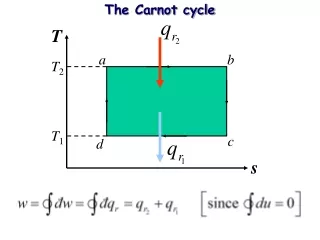
Boundary conditions Table.1. Boundary conditions and operational constraints. Fig.2. T-s diagram for an ORC system.
Working fluid selection • Selection of the working fluid influences efficiency. • Cost of the system depends on the roundtrip efficiency achieved. • Commonly used refrigerants are environmentally hazardous.
Many suitable hydrocarbons have a very high GWP and a non-zero ODP. • Hydro-fluoro-olefins (HFOs) are characterized by very low GWP and zero ODP. • Pressure drop over the expander defined by BCs.
Table.2. Working fluid chemical properties and relative power.
R1234ze(Z) and R1336mzz(E) are found to be the most promising working fluids. • Very low GWP • Zero ODP • Achieves required pressure drop.
Model description • Steady state Python model of an ORC system. • Fluid property database from REFPROP v10. • Non-linear interior point optimization solver – IPOPT. • Sensible & latent heat thermal energy storage (SH-TES, LH-TES) considered.
Working fluid is preheated in SH-TES to the point of saturation. • Working fluid phase transition and superheating takes place LH-TES. • Better match between the thermal profiles of the working fluid and the TES system reduces exergy destruction.
Efficiency is 7.58% with R1336mzz(E) and 8.83% with R1234ze(Z) while 8.4% for R245fa. • Heat transferred from PCM to the working fluid twice as high when R1234ze(Z) is used. • Net power obtained for R1336mzz(E) is 14.2 kW and for R1234ze(Z) this is 21.9 kW.
The ratio of latent heat transfer rate to the sensible heat transfer rate for R1234ze(Z) is 0.96, whereas for HFO-1336mzz(E) it is 0.57. • The heat transferred in the LH-TES increases by 77% with R1234ze(Z), but the net work obtained also increased by 54%.
Exergy available at the inlet of the heat source for R1234ze(Z) is 38% higher but also higher exergy losses. • The total exergy destroyed increases by 73% & 46% for R1234ze(Z) and R245fa respectively.
conclusion • Work and Heat exchange: • Almost similar cycle efficiency with R1336mzz(E) and R1234ze(Z). • Amount of heat transferred from the TES to the working fluid is twice for R1234ze(Z). • The ratio of latent heat transfer rate to the sensible heat transfer rate higher for R1234ze(Z).
Much larger PCM storage is needed for R1234ze(Z). • The net power obtained from the cycle is higher for R1234ze(Z).
Exergy Loss: • Loss in exergy reduced by two-stage TES system. • The exergy available at the inlet of the heat source is higher for R1234ze(Z). • The total exergy destruction increases by 73% for R1234ze(Z). • The losses in exergy are also very high for R1234ze(Z).
Aditya PillaiPhD StudentAPPLIED THERMODYNAMICS & HEAT TRANSFER LABE aditya.pillai@ugent.beM +32 474 47 18 02www.ugent.be • Universiteit Gent@ugent • @ugentGhent University