The Transport Layer
310 likes | 462 Vues
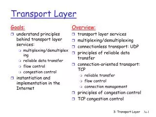
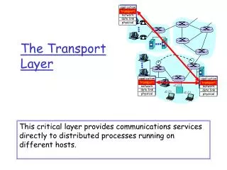
The Transport Layer. Chapter 6. The Transport Service. Services Provided to the Upper Layers Transport Service Primitives Berkeley Sockets. Services Provided to the Upper Layers. The network, transport, and application layers. Why the transport layer ?.

The Transport Layer
E N D
Presentation Transcript
The Transport Layer Chapter 6
The Transport Service • Services Provided to the Upper Layers • Transport Service Primitives • Berkeley Sockets
Services Provided to the Upper Layers The network, transport, and application layers.
Why the transport layer ? 1. The network layer exists on end hosts and routers in the network. The end-user cannot control what is in the network. So the end-user establishes another layer, only at end hosts, to provide a transport service that is more reliable than the underlying network service. 2. While the network layer deals with only a few transport entities, the transport layer allows several concurrent applications to use the transport service. 3. It provides a common interface to application writers, regardless of the underlying network layer. In essence, an application writer can write code once using the transport layer primitive and use it on different networks (but with the same transport layer).
Transport Service Primitives The primitives for a simple transport service.
Transport Service Primitives (2) The nesting of TPDUs, packets, and frames.
Transport Service Primitives (3) A state diagram for a simple connection management scheme. Transitions labelled in italics are caused by packet arrivals. The solid lines show the client's state sequence. The dashed lines show the server's state sequence.
Berkeley Sockets The socket primitives for TCP.
Elements of Transport Protocols • Addressing • Connection Establishment • Connection Release • Flow Control and Buffering • Multiplexing • Crash Recovery
Transport Protocol Both data link layer and transport layer do error control, flow control, sequencing. The differences are: 1. Storage capacity in subnet. Frames must arrive sequentially, TPDUs can arrive in any sequence. 2. Frames are delivered to hosts, TPDUs need to be delivered to users, so per user addressing and flow control within the hosts is necessary. (a) Environment of the data link layer. (b) Environment of the transport layer.
Addressing TSAPs (Transport Service Access Point) , NSAPs (Network SAP). TCP calls TSAP s ... ports ATM calls TSAPs ... AAL-SAP
Connection Establishment (1) How a user process in host 1 establishes a connection with a time-of-day server in host 2.
Connection Establishment (2) Three protocol scenarios for establishing a connection using a three-way handshake. CR denotes CONNECTION REQUEST. (a) Normal operation, (b) Old CONNECTION REQUEST appearing out of nowhere. (c) Duplicate CONNECTION REQUEST and duplicate ACK.
Connection Establishment (3) (a) TPDUs may not enter the forbidden region. (b) The resynchronization problem.
Connection Release Abrupt disconnection with loss of data.
Connection Release (2) The two-army problem.
Connection Release (3) 6-14, a, b Four protocol scenarios for releasing a connection. (a) Normal case of a three-way handshake. (b) final ACK lost.
Connection Release (4) 6-14, c,d (c) Response lost. (d) Response lost and subsequent DRs lost.
Flow Control and Buffering Dynamic buffer allocation. Buffer allocation info travels in separate TPDUs. The arrows show the direction of transmission. ‘…’ indicates a lost TPDU. Potential deadlock if control TPDUs are not sequenced or timed out
Multiplexing • Upward multiplexing. • Downward multiplexing. Used to increase the bandwidth, e.g., two ISDN connections of 64 kbps each yield 128 kbps bandwidth.
The Internet Transport Protocols: UDP • Introduction to UDP • Remote Procedure Call • The Real-Time Transport Protocol
Introduction to UDP UDP only provides TSAPs (ports) for applications to bind to. UDP does not provide reliable or ordered service. The checksum is optional. The UDP header.
Remote Procedure Call Steps in making a remote procedure call. The stubs are shaded.
The Real-Time Transport Protocol (a) The position of RTP in the protocol stack. (b) Packet nesting.
The Real-Time Transport Protocol (2) The RTP header. X indicated the presence of an extension header. CC says how many contributing sources are present (0 to 15). Syn. Source Id. tells which stream the packet belongs to. For feedback information is used an associated protocol called RTCP (Real Time Control Protocol)
The Internet Transport Protocols: TCP • Introduction to TCP • The TCP Service Model • The TCP Protocol • The TCP Segment Header • TCP Connection Establishment • TCP Connection Release • TCP Connection Management Modeling • TCP Transmission Policy • TCP Congestion Control • TCP Timer Management • Wireless TCP and UDP • Transactional TCP
The TCP Service Model Port Protocol Use 21 FTP File transfer 23 Remote login Telnet E-mail 25 SMTP 69 Trivial File Transfer Protocol TFTP Finger Lookup info about a user 79 80 World Wide Web HTTP POP-3 110 Remote e-mail access USENET news 119 NNTP Some assigned ports.
The TCP Service Model (2) (a) Four 512-byte segments sent as separate IP datagrams. (b) The 2048 bytes of data delivered to the application in a single READ CALL.
TCP Service Model (3) All TCP connections are full-duplex and point-to-point. TCP provides a byte stream. i.e it does not preserve message boundaries At sender TCP may immediately send or buffer data at its discretion. Sender can use a PUSH flag to instruct TCP not to buffer the send. Sender can use URGENT flag to have TCP send data immediately and have the receiver TCP signal the receiver application that there is data to be read.
Some TCP features Every byte has its own 32 bit sequence number. Sending and receiving entities exchange data in segments Each segment is the 20 byte header and data (total up to 64K) TCP may aggregate multiple writes into one segment or split one write into several segments. A segment size if the smaller of either 64K or the MTU of the network layer (MTU of Ethernet is about 1500 bytes) A segment must fit in a single IP payload.
Some TCP features TCP uses the sliding window protocol as its base. Sender sends segment, starts timer waits for ack. It no ack then retransmit. Receiver acks in separate segment or “piggyback” on data segment. TCP must deal with reordred segments. A lot of algorithms have been developed to make TCP efficient under diverse network conditions. We will look at a few of them.