COMPUTER AIDED ENGINEERING
COMPUTER AIDED ENGINEERING. ENGI 7928 Finite Element Modelling and Simulation Part-1. Modeling & Simulation. System A system exists and operates in time and space. Model Simplified mathematical representation of the actual system Promotes understanding of the real system.

COMPUTER AIDED ENGINEERING
E N D
Presentation Transcript
COMPUTER AIDED ENGINEERING ENGI 7928 Finite Element Modelling and Simulation Part-1
Modeling & Simulation System • A system exists and operates in time and space. Model • Simplified mathematical representation of the actual system • Promotes understanding of the real system.
Modeling & Simulation (contd.) Simulation • Computerized version of the model which is run over time to study the implications of the defined interactions. • One develops a model, simulates it, learns from the simulation, revises the model, and continues the iterations until an adequate level of understanding is developed.
Simplified Representation of System • Lumped Parameter Model versus Continuous Model • Dimensional Simplification • 1-D Model • 2-D Model • 3-D Model • Symmetric Simplification • Non-symmetric Model • Axisymmetric Model • Quarter Symmetric Model
Simplified Representation of System (contd.) • Condition of Dimensional simplification • Plane stress problem • Plane strain problem • Plane stress with thickness problem • Condition of Symmetry • Geometric symmetry • Symmetric displacement constraint • Traction boundary condition
What are the details needed to do a Finite Element Analysis? • Geometry of the component or structure • Shape • Size (Dimensions) • Material out of which the structure is made • Boundary Conditions • Loads acting on the structure • Expectations from the problem (How do you expect the structure to respond from the description of the above details?) - This would help you in deciding the type of analysis required, select the element and also check the results of the analysis The geometry is generated by modelling. Shape and Size are the two basic parameters that define the geometry of the structure.
Finite Element Analysis of Model • Create Geometry of Model • Define Element Type • Define Material Properties • Define Geometric Properties • Assign the Appropriate Properties to the Exact Area
Finite Element Analysis of Model (contd.) • Apply Boundary Conditions • Apply Loads • Dividing the Model into Number of Elements • Meshing (Connectivity of elements) • Solution • Post-Processing (Analysis of the Result from Simulation)
FEA Process Map Criteria for Element Selection Structural/Thermal etc Physical Problem Material Behaviour Decide on type of Analysis Required 1-D/2-D/3-D Analysis Pre-Processing Element Selection Reqd. DOF to analyze the Expected behaviour Geometric Modelling Symmetry Considerations Meshing Define Material Prop. Applying Loads and Boundary Conditions Solution Viewing Results / Post-Processing
Element Type • The common element types are as below • Line or Spar Elements • Beam Elements • Plane Elements • Shell Elements • Solid Elements • The elements are classified based on the physical behaviour they are bound to represent, type of analysis (structural, thermal, coupled field etc), material property, whether they need to be modeled over a line or area or volume model etc.
Define Material Properties • Modulus of Elasticity • Poisson Ratio • Strain Rate • Stress-strain curve • Yield strength
Define Geometric Properties • Cross-sectional Area • Thickness • Moment of inertia
Boundary Conditions Boundary conditions are needed to: • Restrain the model so that rigid body motion does not occur. • Constraints depends on degrees of freedom. Examples of types of constraints are: Displacement: ux, uy, uz (translation along X, Y, Z) Rotation: rotx, roty, rotz (rotation with respect to X, Y, Z) Symmetric Boundary Condition • Successful analysis depends on how closely users approximate reality in geometry, material behavior, loads, and boundary conditions.
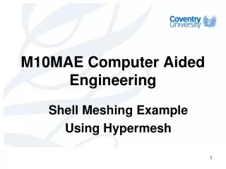
Meshing • Meshing is the process of discretizing the domain with the selected elements • The successful analysis has a greater dependence on the quality of the mesh.
Meshing(contd.) The general meshing guidelines are: • Use coarse mesh on the first run and then refine it on subsequent runs to check the variation of the result with increase in mesh density. Making a finer mesh increases the number of nodes and elements and hence the computational time. • Use fine mesh in the primary areas of interest and in the regions of high field gradient (areas of stress concentration, areas where there is abrupt change in geometry etc.)
Poor Meshing (contd.) Good
Post-Processing • Contour Plots • List of data for further analysis • Nodal data • Element data
COSMOS COSMOS Works is a design analysis automation application fully integrated with Solid Works. This software uses the Finite Element Method (FEM) to simulate the working conditions of your designs and predict their behaviour. FEM requires the solution of large systems of equations. Powered by fast solvers, COSMOS Works makes it possible for designers to quickly check the integrity of their designs and search for the optimum solution.