Download
1 / 7
70 likes | 206 Vues
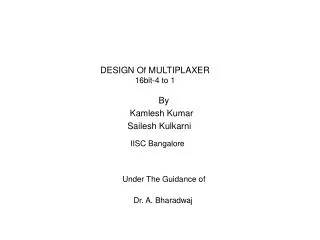
DESIGN Of MULTIPLAXER 16bit-4 to 1. By Kamlesh Kumar Sailesh Kulkarni IISC Bangalore Under The Guidance of Dr. A. Bharadwaj. Block Digram Of Mux.

E N D
DESIGN Of MULTIPLAXER 16bit-4 to 1 By Kamlesh Kumar Sailesh Kulkarni IISC Bangalore Under The Guidance of Dr. A. Bharadwaj
Objective: The aim is to add this module in the planed tape out to optimize the no of pins as per as area and cost. Discription: This mux has 4 inputs (each 16-bits) and the 16-bits output and 4 selection inputs. The functionality of this module is describe in following points. • As the NITK_RST_IN becomes zero and all the other Reset inputs are high, The NITK_ADC_Block will select. Since NITK_ADC_Block has only 7-bit input the remaining upper 9-bit input will be fixed at high. The out put will be available at lower 7-bits of the mux_out. • As the PSG_FFT_RST_IN becomes zero and all the other Reset inputs are high, The PSG_FFT_Block will select. Since PSG_FFT_Block has only 8-bit input the remaining upper 8-bit input will be fixed at high. The out put will be available at lower 8-bits of the mux_out. • As the PSG_LFSR_RST_IN becomes zero and all the other Reset inputs are high, The PSG_LFSR_Block will select. Since PSG_LFSR_Block has only 12-bit input the remaining upper 4-bit input will be fixed at high. The out put will be available at lower 12-bits of mux_out. .
4. As the PSG_MULT_RST_IN becomes zero and all the other Reset inputs are high, The PSG_MULT_Block will select. Since PSG_MULT_Block has complete 16-bit input all of them will be available at 16-bits of mux_out.The following table will summarize all possible reset inputs and according to their output.
What is the maximum clock frequency of each block? Top level clock tree buffering for blocks which need clock signal. ( Each block must have their clock skew balanced internally ) We need the block outline with port definition along with power and ground. Power I/O VDD_IO - Cells which can be used are as VDD3RP ( core logic + periphery cells) VDDA - AVDDALLP VDD - VDD3IP (core logic) GND - GND3ALLP GNDA - AGNDALLP Signal IO INPUT - ICP, ICUP OUTPUT - BU1P , BU16P I/O_A -APRIOP , APRIOWP, APRIO50P , APRIO200P Cell dimension – 100um x 340 um