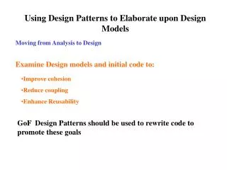
CAD Design Basics with ProEngineer: Step-by-Step Tutorial
Learn how to design CAD models using ProEngineer, covering basics like sketching, planes, and dimensioning tools. Choose from different difficulty levels: Hard (no help), Medium (minimum help), and Easy (step-by-step support). Check out demos for advanced learning. Enhance your skills by creating a robot model with detailed instructions. Explore datum planes, coordinate systems, and axis creation. Start your CAD journey with ProEngineer today!

CAD Design Basics with ProEngineer: Step-by-Step Tutorial
E N D
Presentation Transcript
How to Design using ProEngineer Dionna Harvell CEP 811 12/5/2010
INTRODUCTION How to Design using ProEngineer will help students at different CAD levels • learn the basics to creating models in CAD • learn how to make start parts in Pro-E • create sketches, align planes, axis, csys, and dimensioning tool
WHICH LESSON WOULD YOU LIKE? HARD (no help) BOAT MEDIUM (minimum help) CAR (2) ADVANCED ProEngineer DEMO • http://m.youtube.com/watch?gl=US&client=mv-google&hl=en&v=E9Vc7wgE-jI • http://m.youtube.com/watch?gl=US&client=mv-google&hl=en&rl=yes&v=_yj3vaLogU4 EASY (step by step help) ROBOT *NOTE: If you are interested in a more advanced CAD course after reviewing the 2 demos and successfully completing the quizzes contact me at dionnaharvell@gmail.com
Setting Up Start Fileinches (or) millimeters • Once you have chosen your file name and file extension, you must indicate if you would like your start file to be drawn in inches or millimeters. You can also enter the parameters at this time or you can enter them later in the file, see below. • Click tools – Parameters (enter information) • Every Start assembly and part should have the following: • XYZ - Datum Planes • XYZ - Coordinate System • Center Axis
DATUM PLANES Datum planes are features used to provide references for other features, like sketching planes, dimensioning references, view references, assembly references, and so on. Datum planes are not physical parts of the model, but are used to aid in model creation. • Through • the datum must pass through an existing surface, axis, edge, vertex, or cylinder • Normal • the datum is perpendicular to a surface, axis, or other datum • Parallel • the datum is parallel to another surface or plane • Offset • the datum is parallel to another surface or plane and a specified distance away • Angle • the datum is at a specified angle from another plane or surface • Tangent • the datum is tangent to a curved surface or edge
COORDINATE SYSTEM • A system which uses one or more numbers, or coordinates, to uniquely determine the position of a point or other geometric element
AXIS (also called a rotational axis). • An imaginary line around which an object can be rotated a certain number of degrees and still resemble the original shape. When two planes of symmetry intersect, they form a straight line, which is the axis of symmetry.
Create the Part Creating Part File Go to FILE – NEW (TEXT BOX APPEARS) When starting a new file you have to give it a file name & extension type, (.asm, .prt, .drw, etc). For instance, robot.asm, would be the assembly file (parent file) and arms.prt would be the part file (child).
Create the Head (click on image for more details or larger view )
SKETCH • A sketch is a rapidly executed freehand drawing that is not intended as a finished work. • Use sketch entities to develop the shape • Constrain, dimension, and extrude geometry from a sketch • You can not create a part or component in ProEngineer without making a sketch first.
This time add a rectangular sketch and instead of extruding you are going to remove material this time to create mouth.
Create the Body (click on image for more details or larger view)
Create a sketch to remove material or you can use the chamfer tool
Create the Assembly Creating An Assembly File
Create the Assembly Creating An Assembly & Part File Go to FILE – NEW (TEXT BOX APPEARS) When starting a new file you have to give it a file name & extension type, (.asm, .prt, .drw, etc). For instance, robot.asm, would be the assembly file (parent file) and arms.prt would be the part file (child).
Robot Assembly Start with your assembly (.asm) start file, then insert your part (.prt) files. You can not insert the .prt file into the .asm file.
Robot Assembly To create the Robot assembly start with an empty assembly Insert component and add your first (head) component and fully constrain Insert component and add your body component and fully constrain to the head Insert component and add your arms and fully constrain to the body Last, Insert component and add your legs and fully constrain to the body
This ends the ROBOT lesson are you ready to go to Lesson 2 YES or NO
Create the Car BodyClick for more details on new features in this lesson
Mirror function when using the mirror function select the object you want to mirror and then the datum or axis to mirror around
Offset Datums You will get this command box, choose the datum you want to offset and click ok, you can offset at a certain distance or to a surface. Play around with it to create revolve datums when you get time.
Create the Wheels Click for more details on new features in this lesson
Create the Seats Click for more details on new features in this lesson
Create the Steering Wheel Click for more details on new features in this lesson
When using the revolve feature make sure to add a horizontal or vertical axis to revolve around.
This ends the CAR lesson are you ready to go to Lesson 3 YES or NO
Create the Boat Hull 2.00” thickness, be creative with the hull design!!!
Create the Boat Mast Try out different lengths and diameters!!!
Create the Boat Boom Try out different lengths and diameters!!!
Create the Boat Main Sail Try out the Protrusion feature, and play around with changing the sail colors.