OVERHEAD LINE INSULATORS
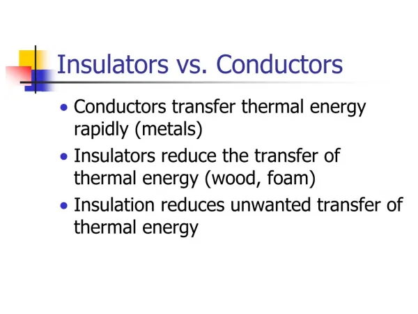
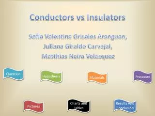
OVERHEAD LINE INSULATORS. ● The insulators for overhead lines provide insulation to the power conductor from ground. ●The insulators are connected to the cross arm of the tower and the power conductor passes through the clamp of the insulator. Cross arm. Insulator.

OVERHEAD LINE INSULATORS
E N D
Presentation Transcript
●The insulators for overhead lines provide insulation to the power conductor from ground. ●The insulators are connected to the cross arm of the tower and the power conductor passes through the clamp of the insulator.
Cross arm Insulator
Characteristics of Solid Insulators • High Mechanical strength. • High Electric strength. • High insulation resistance. • Free from impurities and moisture. • Air and gas free (decrease the dielectric strength) • Withstand the flashover phenomenon.
Insulator Materials 1- Toughened Glassالزجاج المقسّى ● Glass is cheaper than porcelain ● Electric Strength is 140 kV/cm ● It has lower coefficient of thermal expansion which reduces the strains due to temperature changes ● Moisture condenses on the surface increases the leakage current ● Glass insulators are used up to 33 kV lines.
2- Porcelain ● Mechanical strength is higher than glass ● Low leakage current ● Less effected by temperature ● Electric strength is 60 kV/cm ● Used with any number of units to increase the insulation level
Insulation Failure • High Mechanical stress on insulator. • Defects in insulator material (air, gases, impurities) • Flashover of insulator (due to over voltages): The flashover voltage is the voltage which will cause an arc through the air surrounding the insulator. The arc heat can damage the insulator ( the insulators are fitted with arcing horns to keep the arc away from the insulator). ● Faults (short circuits)
Types of Insulators 1- Pin Type Insulators ( (العوازل المسمارية ● Pin type insulator consists of a single or multiple units. ● They are used only up to 33 kV. ● For higher voltages the pin type insulators are very heavy and more costly.
Double- unit pin insulator 33 kV Single- unit pin insulator 11 kV Metal pin
2- Suspension Insulators ( عوازل التعليق): ● Suspension insulator consists of porcelain disc units mounted one above each other. ● Each disc is provided with a metal cap at the top and a metal pin under. ● a string of any number of units can be built according to the line operating voltage . ● The conductor is suspended below the point of support by means of insulator string
The number of discs in a string depends on the line voltage and the atmospheric conditions (degree of pollution). • The usual number of discs are: Voltage (kV) : 66 132 220 400 Number of discs: 4-5 9-10 15-16 22-23
Insulator disc (unit) Insulator string
3- Strain Insulators ( عوازل الأجهاد) ●These are special mechanical strong suspension insulators. ● They are used to take the tension of the conductors at the line terminals, at angle towers, and at road crossings. ● The strings are placed in horizontal plane. ● Two or three strings of insulators in parallel can be used when the tension in conductors is very high.
Arcing horns are used to protect insulators on high voltage Lines from damage during flashover. Over voltages on transmission lines, due to switching operations, lightning, or electrical faults can cause arcs across insulators (flashovers) that can damage them. The horns makes the flashover to occur between themselves rather than across the insulator surface. Horns are normally paired on either side of the insulator, one connected to the line and the other to ground.
Arcing horn Strain Insulator with arcing horn
Voltage Distribution over Insulator Ground or Tower Conductor
Cs : capacitance of each insulator unit. Ce =m Cs : capacitance to ground is the capacitance of metal part of the insulator unit to the tower (m<1). V1, V2, V3the voltage across each unit starting from the cross arm towards the power conductor. V = V1 + V2 +V3 Line voltage
At point A: I2 = I1 +i1 ωC.V2 = ωC.V1 + ωmC.V1 V2 = (1+m).V1 At Point B: I3 = I2 + i2 ωC.V3 = ωmC.(V1+V2) + ωC.V2 V3=m.V1 +(1+m).V2 =(m +(1+m)2).V1 V3 = (1+3m +m2).V1
For m < 1 V3 > V2 > V1 Insulator Efficiency: η = (V/n.Vmax) x 100 V: Voltage across the insulator string, (phase Volt) n: number of insulator units. Vmax: Voltage across the insulator unit near to the power line (for n = 3, Vmax = V3).
In general, voltage across the units is given by: Vn+1 = Vn.(1+m) + (V1+V2+……+ Vn-1).m n= 1 V2 = (1+m). V1 n=2 V3 = V2.(1+m) + V1.m n=3 V4 = V3.(1+m) + (V1 +V2).m n=4 V5= V4.(1+m) + (V1 + V2 +V3).m
The voltage across the units cam also given by: n= 1 V2 = (1+ m). V1 n=2 V3 = (1+ 3 m +m2). V1 n=3 V4 = V3.(1+ 6 m +5 m2 + m3). V1 n=4 V5= V4.(1+ 10 m + 15 m2 + 7m3 + m4 ). V1
Example An insulator string for 66 kV line has 4 units. The capacitance to ground is 10% of the capacitance of each insulator unit. Find the voltage across each insulator unit and string efficiency.
V2 = (1+m). V1 = 1.1 V1 V3 = V2.(1+m) + V1.m = 1.31 V1 V4 = V3.(1+m) + (V1 +V2).m =1.651 V1 V1 +V2 +V3 +V4 = = 38.1 kV V1 (1+1.1 +1.31+1.651)=38.1 V1=7.53 kV, V2= 8.28 kV, V3=9.86 kV, V4= 12.43 kV String efficiency = (38.1/4x12.43)x100=76.6%
Example Find the voltage distribution of an insulator of 3 units, if the maximum voltage of each unit is 17 kV, and the capacitance to ground is 20% of unit capacitance, also find the insulator efficiency.
V3 = 17 kV, m=20% = 0.2 V2 = (1+m).V1 = 1.2 V1 V3 = V1.m+ V2.(1+m) =1.64 V1 V1 = 17/1.64 = 10.36 kV V2 = 1.2x10.36 = 12.43 kV V= V1 + V2 + V3 = 39.8 kV Insulator efficiency = (39.8/3x17)x100=78.03%
Improvement of String EfficiencyMethods of Equalizing Potential (p.386) 1- Reducing the ground capacitance relative to the capacitance of insulator unit (reduce m where m = ce/cs): This can be done by increasing the length of cross arm and hence taller supporting tower which uneconomical.
Improvement of String Efficiency 2- Grading of insulator units: It can be seen that the unequal distribution of voltage is due to the leakage current from the insulator pin to the tower structure. The solution is to use insulator units with different capacitances. This requires that unit nearest the cross arm should have minimum capacitance (maximum Xc) and the capacitance should increase as we go towards the power line.
This means that in order to carry out unit grading, units of different types are required. This requires large stocks of different units which is uneconomical and impractical.
Improvement of String Efficiency 3- Static Shielding (Guard Ring): ( حلقة الحماية) This method uses a large metal ring surrounding the bottom insulator unit and connected to the line. This ring is called a grading or guard ring which gives a capacitance which will cancel the charging current of ground capacitance.
Guard ring serves two purposes: • Equalizing the voltage drop across each insulator unit. • protects the insulator against flash over.