Download

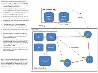
1 / 30
300 likes | 413 Vues
Protection of UNIs and E-NNIs. Zehavit Alon Nurit Sprecher September 2009. The comparison indicted that mesh is superior to ring. Recap.

E N D
Protection of UNIs and E-NNIs Zehavit Alon Nurit Sprecher September 2009
The comparison indicted that mesh is superior to ring. Recap • The subject of Inter-network Ethernet Service Protection was introduced during the meeting in May in: http://www.ieee802.org/1/files/public/docs2009/new-alon-service-protection-in-interconnectned-areas-0509-v01.ppt • Two possible topologies were introduced and compared • Mesh • Ring
Recap (cont’d) • The mesh topology has advantages and drawbacks: • Advantages • Direct (single-hop) connectivity between the attached networks ensuring a short path and low latency during transmission between the attached networks • Capability to enable efficient and simple load-sharing across all the (direct) links with optimum resource utilization • Drawback Any protection event (i.e. switchover or revert) in the interconnected zone affects the topology of at least one of the attached networks.
Drawback overcome • Note: A construct with 5 links is also supported. The left side operates like the partial mesh topology while the right side behaves like the full mesh topology. Full Mesh Partial Mesh
Drawback overcome (cont’d) The full mesh construct benefits from the advantages of the mesh. It minimizes the effects of protection events within the interconnected zone on the topology of the related attached networks, reducing them to the level of inevitable effects: • Each protected VLAN is transported over one of the links traversing the interconnected zone. • Topology changes in the attached network are minimized by (when possible) using the connectivity between the node in the same network.
TG TG TG TG TG TG TG TG Reminder and definitions • The protection mechanism provides local protection of Ethernet services (VLANs) between network boundaries. • The nodes, ports, and links connecting the adjacent networks are referred to as the interconnected zone. • The node in each of the networks which at any given moment conveys traffic from the network to the interconnected zone, as well as from the interconnected zone to the network, is referred to as the traffic gateway (TG). Example route Interconnected Zone Interconnected Zone Interconnected Zone Interconnected Zone
Requirements • Protect against any single failure or degradation of a facility (link or node) in the interconnected zone • Support all standard Ethernet frames: 802.1D, 802.1Q, 802.1ad, 802.1ah • Support interconnection between different network types (e.g. CN-PBN, PBN-PBN, PBN-PBBN, PBBN-PBBN, etc.) • Provide 50ms protection switching • Provide a clear indication of the protection state • Maintain an agnostic approach regarding • the Ethernet technology running on each of the interconnected networks, and • the protection mechanism deployed by each of the interconnected networks
Requirements (cont’d.) • Avoid modification of the protocols running inside each of the interconnected networks • Ensure that multicast and broadcast frames are delivered only once over the interconnected zone • Allow load-balancing between the interfaces that connect the networks to ensure efficient utilization of resources • Minimize the effects of protection events within the interconnected zone on the topology of the related attached networks, reducing them to the level of unavoidable effects
Solution PrinciplesFailure effects • When a traffic gateway node fails, changes in the attached network (to which the node belongs) are inevitable. • A new node becomes the traffic gateway replacing the failed traffic gateway.
Solution PrinciplesFailure effects • When a link between traffic gateway nodes fails, a bypass route may (when possible) be established between the nodes to prevent changes in the attached network (replacing the failed link, while keeping the traffic gateways).
S S Solution PrinciplesNode roles • For each protected VLAN, a node in one network is connected to the nodes in the other network. This node, referred to as the master, is responsible for selecting the link over which the traffic will be conveyed between the networks. • The master is connected to two nodes in the adjacent network. These two nodes follow the master’s decisions and are referred to as slaves. M
The role of each node (master, deputy, and slave) is set for each VLAN by administrative configuration. • The same node may function as a master node for some VLANs (blue), as a deputy node for other VLANs (red), and as a slave for other VLANs (green), thus enabling load-sharing between the nodes. Solution PrinciplesNode roles (cont’d) • The master can be protected by a redundant node which may replace the master as the decision-making node. This node is referred to as the deputy. The deputy is connected to the same two slaves as the master. • The master and deputy are referred to as control nodes. M S S D S D D S M S M S
Solution PrinciplesPort configurations In the control nodes, one of the ports connecting the networks is configured as working, the other as protection. • The working port is the preferred port (administratively enabled) for conveying traffic in the absence of other considerations. (A consideration that precedes port configuration is the preservation of the traffic gateway.) • The slaves have no configurations on these ports. Master Slave1 W P W P Deputy Slave2
Solution Principles Additional (optional) connectivity The nodes on the same network may also be connected: • Slave nodes - provide a means to bypass a failed link without changing the traffic gateway. • Control nodes (master and deputy) provide direct health monitoring between the control nodes. Master Slave1 Deputy Slave2
Solution PrinciplesAdditional port configuration The ports connecting the control nodes to each other are configured as internal. This also applies to the ports connecting the slave nodes to each other. Internal ports are optional. • An internal port may be configured on all node types (master, deputy, and slave). • The state “absent” is used when there is no internal port. (This state distinguishes the configuration from that in which an existing internal link failed. In both cases, the port does not receive a message form its peer.) Master Slave1 W I P I I I W P Deputy Slave2
Solution HighlightsMaster • The master becomes a traffic gateway: • Always when it operates in revertive mode • If the deputy is not already a traffic gateway in non-revertive mode • The master chooses the port for conveying traffic according to: • Existence of a traffic gateway amongst the slaves • Port configuration and link states (in the absence of a traffic gateway) Master Slave1 W I P I I I W P Deputy Slave2
The master behaves in the same way. The slave decides whether or not to form a bypass. Solution PrinciplesSlaves A slave that receives a request to become a traffic gateway from a control node will: • become a traffic gateway: • when there is an internal link, and the other slave is not a traffic gateway • when the internal link is absent • become an intermediate node in a bypass that redirects traffic to the other slave • when there is an internal link, and the other slave is a traffic gateway Master Slave1 W I P I I I W P Deputy Slave2
Master Slave1 Master Slave1 W W I P I P I I W W P P Slave2 Deputy Slave2 Deputy Solution HighlightsDeputy • The deputy becomes a traffic gateway: • immediately, when it looses connectivity with the master (when the control nodes are connected) • when there is no traffic gateway amongst the slaves for a predetermined period of time (which indicates that there is no traffic gateway amongst the control nodes) and the control nodes are not connected • The deputy chooses the port to convey traffic according to: • the existence of a traffic gateway amongst the slaves • port configuration and link states (in the absence of a traffic gateway)
W W D M D M P P Note: Node revertive may have an effect on the attached networks - TG changed. Note: Port revertive may have an effect on the attached networks - TG changed. Solution principles Revertive modes • Revertive mode is supported by the control nodes at 2 levels: port level and node level W P1 S1 • Port-level revertive mode Traffic is restored to the configured working port. • Node-level revertive mode Traffic is restored to the master after it recovers from a failure. P P2 I I I I P1 S2 P2 W P1 S1 P P2 I I I I W P1 S2 P2
M S1 D S2 Transition table Note 1: A bypass to a failed link always goes through a slave (never through a control node). Note 2: The last two columns are for constructs that only have five links. (The control nodes are not connected.) Note 3: The scenario in which there are only four links can be reached, when applicable, by removing the S1 S2 connectivity.
S M D S S S AA S S State machine • Each node retains its own state (TG or not) and the states (active/standby) of its ports (P1, P2, and I) which are part of the interconnected zone. • The node is updated on the state of the peer ports and the nodes connected to it via information received over the links connected to the other nodes. • Each node may change its own state and the state of its ports according to the configuration, the state of the node and the ports, and according to the information received. P1 P2 I S S
A A S S A A S S SS AS S S S1 A S A S S S AS S S D M S S S S S S S S S S S S Start Up The master changes its state to active, becomes a traffic gateway, and chooses the working port to convey traffic. It creates new messages and sends them over the ports The slave receives a request on P1 to become a traffic gateway. It changes its state to active to become a traffic gateway, and chooses the port on which the request arrived (P1) for conveying traffic. It creates new messages and sends them over its ports. The master receives an indication from the slave that it became a traffic gateway using port P1. It does not change its state or the messages it sends over its ports. Beginning The scenario start when all nodes are started for the first time; no traffic is conveyed. The nodes start with all ports in standby; none acts as a traffic gateway. Master Slave 1 W P1 P P2 I I EndThe mater and Slave 1 are traffic gateways; they use the link connecting the working port of the master and P1 of Slave1. The deputy and Slave 2 are aware of the situation. They do not convey traffic. Deputy Slave 2 I I P1 W S2 P P2 The deputy receives an indication from the master that it is a traffic gateway plus an indication from the slave on the working port that it is also a traffic gateway. The deputy does not change its state and the messages it sends over its ports. The slave receives an indication from the master that it is a traffic gateway but does not receive a request to become a traffic gateway. It also receives an indication from the other slave that it too is a traffic gateway. The slave does not change its state and the messages it sends over its ports.
S S A S A A A A A S A S A S S1 AA A S A S A S AA M D S S S S SA S S S A S S S S S S S S Link fails The link connecting the master and Slave 1 failed. The master does not receive health messages from Slave 1 and realizes that it lost connectivity with it. It chooses the protection port to convey traffic. The slave that acts as a traffic gateway loses connectivity with the master. After a short while, it receives a request over the internal port indicating that the other slave is using it as a bypass. It activates the internal port. BeginningThe scenario starts with traffic being conveyed between the master and Slave 1 using the working port of the master and P1 of the slave. Master Slave 1 W P1 P P2 I I EndThe master and Slave 1 are traffic gateways. Slave 2 is used as an intermediate node in a bypass created between the master and Slave 1. Deputy Slave 2 I I P1 W S2 P P2 The slave receives a request on P1 to become a traffic gateway. It is aware of the fact that the slave connected through the internal port is a traffic gateway. It activates the internal port but does not become a traffic gateway. It will pass all packets received on P1 to the internal port. Packets received from the attached network will be dropped. It creates new messages and sends them over its ports.
S S A A A A A S A S S1 AA A S A S A S D M S S S S A S S S A A S S S S S S A S Slave fails The master does not receive health messages from Slave 1 and realizes that it lost connectivity with it. It chooses the protection port to convey traffic. The slave acting as the TG of this network fails. The master receives an indication from the slave that it became a traffic gateway using port P2. It does not change its state or the messages it sends over its ports. BeginningThe scenario starts with traffic being conveyed between the master and Slave 1 using the working port of the master and P1 of the slave. Master Slave 1 W P1 P P2 I I EndThe master and Slave 2 act as traffic gateways using the link connecting the protection port of the master and P1 of Slave 2. The deputy and Slave 2 are aware of the situation. They do not convey traffic. Deputy Slave 2 I I P1 W S2 P P2 The deputy receives an indication from the master that it is a traffic gateway as well as an indication from the slave on the protection port that it too is a traffic gateway. The deputy is aware that it is not connected to Slave 1. It does not change its state and the messages it sends over its ports. The slave receives a request on P1 to become traffic gateway. It does not have connectivity with Slave 1, so it change its state to active to become a traffic gateway, and chooses the port on which the request arrived (P1) to convey traffic. It creates new messages and sends them over its ports.
A S A A A A A S AA A S S1 A S A S A S D M A S S S S S S S A A S S A S S S S S Master fails Slave 1 senses that it lost connectivity with the master and it receives a request to become a traffic gateway on P2. Since it is already a traffic gateway, it only needs to deactivate P1 and activate P2. It creates new messages and sends them over its ports. The master acting as the TG of this network fails. BeginningThe scenario starts with traffic being conveyed between the master and Slave 1 using the working port of the master and P1 of Slave 1. Master Slave 1 W P1 P P2 I I EndThe deputy is a traffic gateway and conveys traffic using its working port. Slave 1 is a traffic gateway of the attached network and it conveys traffic using P2. Deputy Slave 2 I I P1 W S2 P P2 The deputy senses that the master failed. It becomes a traffic gateway and uses the port that is connected to a slave which is a traffic gateway (if there is such). It creates new messages and send them over its ports.
Proposal Start a new project in the IEEE 802.1 aimed at defining a protection mechanism for Ethernet services in UNI/E-NNI (interconnected networks). • Adopt the proposed topologies. • The mechanism should comply with the requirements introduced in this presentation.
Thank you zehavit.alon@nsn.com nurit.sprecher@nsn.com
Flow Chart M S1 M failed S1 failed M-S2-S1 M S1 D S2 S2 failed D failed M-S2 failed || S1-S2 failed || S2 failed D-S1-S2 D S2 D-S1 failed || S1-S2 failed || S1 failed M1-S1 failed M S1 D-S2 failed M S1 M-S1 S2 D D-S2 D S2 M failed D failed S2 failed || LRM && S1 recovered S1 failed NRM && M recovered ||D failed LRM && M-S1 recovered || S2 failed M M S1 S1 S1 failed M failed M-S2 D-S1 S2 D D S2 M-S2 failed D-S1 failed M-S1 failed ||S1-S2 failed || S1 failed S1-S2 failed ||D-S2 failed || S2 failed M M S1 S1 S2 failed S1 failed D-S2-S1 M-S1-S2 D S2 D S2 D failed M failed