Electromagnetic properties
Electromagnetic properties. Part I. Electrical and magnetic properties. Electromagnetic fields are propagated through and reflected by materials Characterized as: Current flow at low frequencies Magnetism in metals Optical absorbance / reflectance in light etc.

Electromagnetic properties
E N D
Presentation Transcript
Electromagnetic properties Part I
Electrical and magnetic properties • Electromagnetic fields are propagated through and reflected by materials • Characterized as: • Current flow at low frequencies • Magnetism in metals • Optical absorbance / reflectance in light • etc. • Frequency is a major factor in the primary characteristics • Low frequency – “electrical” properties • High frequency – “optical” properties
Fundamentals of high frequency electromagnetic waves (Light) • Light = Energy (radiant energy) • Readily converted to heat • Light shining on a surface heats the surface • Heat = energy • Light = Electro-magnetic phenomena • Has the characteristics of electromagnetic waves (eg. radio waves) • Also behaves like particles (e.g.. photons)
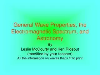
Relationship between frequency and wavelength l Plus Plus Wavelength = speed of light divided by frequency (miles between bumps = miles per hour / bumps per hour) l= Wavelength [m] n= Frequency [Hz] c = 3x10⁸ m/s in a vacuum Minus Minus
Relationship between frequency and wavelength l + - Antenna Plus Plus Minus Minus lKOSU= 3 x 10⁸ / 97.1 x 10⁶ lKOSU= 3 m lred= 6.40 x 10- 7 m = 640 nm Bohr’s Hydrogen = 5 x 10 - 11 m
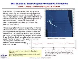
Plants light harvesting structure - model Jungas et. al. 1999
Light emission / absorption governed by quantum effects Planck - 1900 Einstein - 1905 One “photon” DE is light energy flux n is an integer (quantum) h is Planck’s constant n is frequency
Changes in energy states of matter are quantitized Bohr - 1913 • Where Ek, Ej are energy states (electron shell states etc.) and frequency, n , is proportional to a change of state • and hence color of light. Bohr explained the emission spectrum of hydrogen. Hydrogen Emission Spectra (partial representation) Wavelength
Measurement of reflected intensity –Typical Multi-Spectral Sensor Construction One Spectral Channel Photo-Diode detector / Amplifier Analog to Digital Converter CPU Optical Filter Illumination Collimator Radiometer Computer Target
Measurement of reflected intensity - Fiber-Optic Spectrometer One Spectral Channel at a time Optical Glass Fiber Optical Grating Analog to Digital Converter CPU Element selection Computer Photo Diode Array
Visual reception of color • Receptors in our eyes are tuned to particular photon energies (hn) • Discrimination of color depends on a mix of different receptors • Visual sensitivity is typically from wavelengths of ~350nm (violet) to ~760nm (red) Wavelength 700 nm 400 nm 500 nm
Quantification of color • Spectral measurements can be used to quantify reflected light in energy and spectral content, but not very useful description of what we see. • Tri-stimulus models – represent color as perceived by humans • Tri-stimulus models • RGB - most digital work • CYM - print • HSI, HSB, or HSV - artists • CIE L*a*b* • YUV and YIQ - television broadcasts
CIE XYZ model Y • Attempts to describe perceived color with a three coordinate system model X Z= luminance
CIE Lab model • An improvement of the CIE XYZ color model. • Three dimensional model where color differences correspond to distances measured colorimetrically • Hue and saturation (a, b) • a axis extends from green (-a) to red (+a) • b axis from blue (-b) to yellow (+b) • Luminance (L) increases from the bottom to the top of the three-dimensional model • Colors are represented by numerical values • Hue can be changed without changing the image or its luminance. • Can be converted to or from RGB or other tri-stimulus models
Photo-Chemistry • Light may be absorbed and participate (drive) a chemical reaction. Example: Photosynthesis in plants • The wavelength must be correct to be absorbed by some participant(s) in the reaction • Some structure must be present to allow the reaction to occur • Chlorophyll • Plant physical and chemical structure
Primary and secondary absorbers in plants • Primary • Chlorophyll-a • Chlorophyll-b • Secondary • Carotenoids • Phycobilins • Anthocyanins
Chlorophyll absorbance Chla: black Chlb: red BChla: magenta BChlb: orange BChlc: cyan BChld: bue BChle: green Source: Frigaard et al. (1996), FEMS Microbiol. Ecol. 20: 69-77
Radiation Energy Balance • Incoming radiation interacts with an object • and may follow three exit paths: • Reflection • Absorption • Transmission • a + t + r= 1.0 • a, t, andrare the • fractions taking each path • Known as: • fractional absorption coefficient, • fractional transmittance, and • reflectance respectively Il0 Il0r Il0 a Iout = Il0 t
Internal Absorbance (Ai) • Lambert's Law - The amount of light absorbed is directly proportional to the logarithm of the length of the light path or the thickness of the absorbing medium. Thus: l = length of light path k = extinction coefficient of medium • Normally in absorbance measurements the measurement is structured so that reflectance is zero
Reflectance • Ratio of incoming to reflected irradiance • Incoming can be measured using a “white” reflectance target • Reflectance is not a function of incoming irradiance level or spectral content, but of target characteristics
Solar Irradiance NIR UV
Electrical properties - Current and Voltage • Current: • Flow of electrons • The quantity of electrons per unit time flowing through a conducting medium • Units Amperes (A), abbreviated “amps“ or fundamentally coulombs per second (coulomb=6.03x10²³ electrons) • Voltage: • Electromotive force (EMF) • A potential or “tension” between two points of a conducting medium that can drive the flow of electrons through the medium expressed as work per number of electrons • Analogous to pressure in a fluid that can drive flow of fluid through a pipe • Units of Volts (V) or fundamentally joules per coulomb, the energy (potential) per unit of electrons.
Resistors and Ohms Law • Property of a resistor – Flow of current is proportional to voltage (or vice versa). The proportionality constant is known as resistance: • For the following circuit: • Resistance has units of Ohms (W) • (fundamentally, volts per amp) • The current could be computed in the circuit above given Vsupply and R: i = 5V / 10,000W = 0.0005 V = 0.5 mV
Resistivity • The fundamental property of materials defining resistance is resistivity Where: L = length of conductive path A= Crossectional area of conductive path R = Resistance