Download
1 / 51
510 likes | 523 Vues
This section provides an overview of sensor node platforms, sources of energy consumption, and energy management techniques. It discusses various real-life sensor node platforms such as RSC WINS & Hidra, Sensoria WINS, UCLA’s iBadge, and more. The text is in English.

E N D
Part II: Sensor Node Platforms & Energy IssuesMani Srivastava
Sensor Node H/W-S/W Platforms In-node processing Wireless communication with neighboring nodes Event detection Acoustic, seismic, image, magnetic, etc. interface Electro-magnetic interface sensors radio CPU Limited battery supply battery Energy efficiency is the crucial h/w and s/w design criterion
Overview of this Section • Survey of sensor node platforms • Sources of energy consumption • Energy management techniques
Variety of Real-life Sensor Node Platforms • RSC WINS & Hidra • Sensoria WINS • UCLA’s iBadge • UCLA’s Medusa MK-II • Berkeley’s Motes • Berkeley Piconodes • MIT’s AMPs • And many more… • Different points in (cost, power, functionality, form factor) space
Rockwell WINS & Hidra Nodes • Consists of 2”x2” boards in a 3.5”x3.5”x3” enclosure • StrongARM 1100 processor @ 133 MHz • 4MB Flash, 1MB SRAM • Various sensors • Seismic (geophone) • Acoustic • magnetometer, • accelerometer, temperature, pressure • RF communications • Connexant’s RDSSS9M Radio @ 100 kbps, 1-100 mW, 40 channels • eCos RTOS • Commercial version: Hidra • C/OS-II • TDMA MACwith multihop routing • http://wins.rsc.rockwell.com/
Sensoria WINS NG 2.0, sGate, and WINS Tactical Sensor • WINS NG 2.0 • Development platform used in DARPA SensIT • SH-4 processor @ 167 MHz • DSP with 4-channel 16-bit ADC • GPS • imaging • dual 2.4 GHz FH radios • Linux 2.4 + Sensoria APIs • Commercial version: sGate • WINS Tactical Sensor Node • geo-location by acoustic ranging and angle • time synchronization to 5 s • cooperative distributed event processing Ref: based on material from Sensoria slides
Sensoria Node Hardware Architecture Flash RAM Processor 10/100 Ethernet Address/Data Bus Preprocessor Interface Modular Wireless and Digital Interfaces Imager Module Imager Interface RF Modem 1 RF Modem 2 Digital I/O GPS Analog Front End Multi- Channel Sensor Interface DSP Preprocessor Ref: based on material from Sensoria slides
Sensoria Node Software Architecture General Purpose App 1 General Purpose App 2 General Purpose App 3 General Purpose App 4 WINS Node API RF Modem Control Discovery/ Self-Assembly Routing Messaging Geolocation Sensing Signal Processing Inter-Node Ranging Process Management Platform Management Linux 2.4 Kernel RF Modem 1 Interface RF Modem 2 Interface DSP Interface Sensor Interface GPS Interface Acoustic Ranging Interface Platform Interface GPIO Serial RF 1 RF 2 DSP/ ADC GPS Dual Codec uC Ref: based on material from Sensoria slides
Berkeley Motes • Devices that incorporate communications, processing, sensors, and batteries into a small package • Atmel microcontroller with sensors and a communication unit • RF transceiver, laser module, or a corner cube reflector • temperature, light, humidity, pressure, 3 axis magnetometers, 3 axis accelerometers • TinyOS light, temperature, 10 kbps @ 20m
The Mote Family Ref: from Levis & Culler, ASPLOS 2002
TinyOS Messaging Component Internal State Internal Tasks Commands Events • System composed of concurrent FSM modules • Single execution context • Component model • Frame (storage) • Commands & event handlers • Tasks (computation) • Command & Event interface • Easy migration across h/w -s/w boundary • Two level scheduling structure • Preemptive scheduling of event handlers • Non-preemptive FIFO scheduling of tasks • Compile time memory allocation • NestC • http://webs.cs.berkeley.edu Bit_Arrival_Event_Handler State: {bit_cnt} Start Yes Send Byte Eventbit_cnt = 0 bit_cnt==8 bit_cnt++ Done No Ref: from Hill, Szewczyk et. al., ASPLOS 2000
Complete TinyOS Application Ref: from Hill, Szewczyk et. al., ASPLOS 2000
UCLA iBadge • Wearable Sensor Badge • acoustic in/out + DSP • temperature, pressure, humidity, magnetometer, accelerometer • ultrasound localization • orientation via magnetometer and accelerometer • bluetooth radio • Sylph Middleware
Sylph Middleware Speech Recogn. Service Bayesian Fusion Service Storage Service Sensor Apps Sensor Configuration Manager Browsers
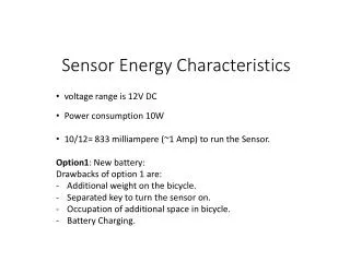
UCLA Medusa MK-II Localizer Nodes • 40MHz ARM THUMB • 1MB FLASH, 136KB RAM • 0.9MIPS/MHz 480MIPS/W (ATMega 242MIPS/W) • RS-485 bus • Out of band data collection, formation of arrays • 3 current monitors (Radio, Thumb, rest of the system) • 540mAh Rechargeable Li-Ion battery
BWRC’s PicoNode TripWire Sensor Node Chip encapsulation (1.5 mm) Solar Cell (0.5 mm) PCB (1 mm) Battery (3.6 mm) 7.6 mm Version 1: Light Powered Components and batterymounted on back 5 cm 3 cm Size determined by power dissipation (1 mW avg) Version 2: Vibration Powered Ref: from Jan Rabaey, PAC/C Slides
BWRC PicoNode (contd.) Sensor/ actuators 16kB CODE Sensor/actuator interface App/UI User interface 4kB XDATA Transport Aggregation/ forwarding 256 DATA DW8051 Chip Supervisor Network Serial Interconnect network Chip Supervisor Locationing DLL (MAC) Energy train FlashIF MAC SIF Serial Baseband ADC GPIO Reactive radio SIF RF (TX/RX) LocalHW PHY ADC Antenna • Reactive inter- and intra-chip signaling • Modules in power-down (low-leakage) mode by default • Events at interface cause wake-up • Hw Modules selected to meet flexibility needs while optimizing energy efficiency (e.g. 8051 microcontroller) 1 mW on < 10 mW sleep Size: 6 mm2 Ref: from Jan Rabaey, PAC/C Slides
Quick-and-dirty iPaq-based Sensor Node! • HM2300 Magnetic Sensor • - uC Based with RS232 • Range of +/- 2Gausus • Adjustable Sampling Rate • X, Y, Z output • Device ID Management • WaveLan Card • IEEE 802.11b Compliant • 11 Mbit/s Data Rate • Familiar v0.5 • Linux Based OS for iPAQ H3600s • JFFS2, read/write iPAQ’s flush • Tcl ported • iPAQ 3670 • Intel StrongARM • Power Management (normal, idle & sleep mode) • Programmable System Clock • IR, USB, Serial (RS232) Transmission • Acoustic Sensor & Actuator • Built-in microphone • Built-in speaker
Sensor Node Energy Roadmap(DARPA PAC/C) 10,000 1,000 100 10 1 .1 • Deployed (5W) Rehosting to Low Power COTS (10x) • PAC/C Baseline (.5W) -Simple Power Management -Algorithm Optimization (10x) Average Power (mW) • (50 mW) -System-On-Chip -Adv Power Management -Algorithms (50x) (1mW) 2000 2002 2004 • Low-power design • Energy-aware design
Where does the energy go? • Processing • excluding low-level processing for radio, sensors, actuators • Radio • Sensors • Actuators • Power supply
Processing • Common sensor node processors: • Atmel AVR, Intel 8051, StrongARM, XScale, ARM Thumb, SH Risc • Power consumption all over the map, e.g. • 16.5 mW for ATMega128L @ 4MHz • 75 mW for ARM Thumb @ 40 MHz • But, don’t confuse low-power and energy-efficiency! • Example • 242 MIPS/W for ATMega128L @ 4MHz (4nJ/Instruction) • 480 MIPS/W for ARM Thumb @ 40 MHz (2.1 nJ/Instruction) • Other examples: • 0.2 nJ/Instruction for Cygnal C8051F300 @ 32KHz, 3.3V • 0.35 nJ/Instruction for IBM 405LP @ 152 MHz, 1.0V • 0.5 nJ/Instruction for Cygnal C8051F300 @ 25MHz, 3.3V • 0.8 nJ/Instruction for TMS320VC5510 @ 200 MHz, 1.5V • 1.1 nJ/Instruction for Xscale PXA250 @ 400 MHz, 1.3V • 1.3 nJ/Instruction for IBM 405LP @ 380 MHz, 1.8V • 1.9 nJ/Instruction for Xscale PXA250 @ 130 MHz, .85V (leakage!) • And, the above don’t even factor in operand size differences! • However, need power management to actually exploit energy efficiency • Idle and sleep modes, variable voltage and frequency
Radio • Energy per bit in radios is a strong function of desired communication performance and choice of modulation • Range and BER for given channel condition (noise, multipath and Doppler fading) • Watch out: different people count energy differently • E.g. • Mote’s RFM radio is only a transceiver, and a lot of low-level processing takes place in the main CPU • While, typical 802.11b radios do everything up to MAC and link level encryption in the “radio” • Transmit, receive, idle, and sleep modes • Variable modulation, coding • Currently around 150 nJ/bit for short ranges • More later…
Computation & Communication Energy breakdown for MPEG Energy breakdown for voice Decode Decode Transmit Encode Encode • Radios benefit less from technology improvements than processors • The relative impact of the communication subsystem on the system energy consumption will grow Receive Receive Transmit Radio: Lucent WaveLAN at 2 Mbps Processor: StrongARM SA-1100 at 150 MIPS
Sensing • Several energy consumption sources • transducer • front-end processing and signal conditioning • analog, digital • ADC conversion • Diversity of sensors: no general conclusions can be drawn • Low-power modalities • Temperature, light, accelerometer • Medium-power modalities • Acoustic, magnetic • High-power modalities • Image, video, beamforming
Actuation • Emerging sensor platforms • Mounted on mobile robots • Antennas or sensors that can be actuated • Energy trade-offs not yet studied • Some thoughts: • Actuation often done with fuel, which has much higher energy density than batteries • E.g. anecdotal evidence that in some UAVs the flight time is longer than the up time of the wireless camera mounted on it • Actuation done during boot-up or once in a while may have significant payoffs • E.g. mechanically repositioning the antenna once may be better than paying higher communication energy cost for all subsequent packets • E.g. moving a few nodes may result in a more uniform distribution of node, and thus longer system lifetime
Power Analysis of RSC’s WINS Nodes • Summary • Processor • Active = 360 mW • doing repeated transmit/receive • Sleep = 41 mW • Off = 0.9 mW • Sensor = 23 mW • Processor : Tx = 1 : 2 • Processor : Rx = 1 : 1 • Total Tx : Rx = 4 : 3 at maximum range • comparable at lower Tx
Some Observations • Using low-power components and trading-off unnecessary performance for power savings can have orders of magnitude impact • Node power consumption is strongly dependent on the operating mode • E.g. WINS consumes only 1/6-th the power when MCU is asleep as opposed to active • At short ranges, the Rx power consumption > T power consumption • multihop relaying not necessarily desirable • Idle radio consumes almost as much power as radio in Rx mode • Radio needs to be completely shut off to save power as in sensor networks idle time dominates • MAC protocols that do not “listen” a lot • Processor power fairly significant (30-50%) share of overall power • In WINS node, radio consumes 33 mW in “sleep” vs. “removed” • Argues for module level power shutdown • Sensor transducer power negligible • Use sensors to provide wakeup signal for processor and radio • Not true for active sensors though…
Energy Management Problem • Actuation energy is the highest • Strategy: ultra-low-power “sentinel” nodes • Wake-up or command movement of mobile nodes • Communication energy is the next important issue • Strategy: energy-aware data communication • Adapt the instantaneous performance to meet the timing and error rate constraints, while minimizing energy/bit • Processor and sensor energy usually less important MICA mote Berkeley WINS node RSC
Processor Energy Management Application PA-API PA-Middleware POSIX PA-OSL Operating System Modified OS Services Operating System PA-HAL Hardware Abstraction Layer Hardware • Knobs • Shutdown • Dynamic scaling of frequency and supply voltage • More recent: dynamic scaling of frequency, supply voltage, and threshold voltage • All of the above knobs incorporated into sensor node OS schedulers • e.g. PA-eCos by UCLA & UCI has Rate-monotonic Scheduler with shutdown and DVS • Gains of 2x-4x typically, in CPU power with typical workloads • Predictive approaches • Predict computtion load and set voltage/frequency accordingly • Exploit the resiliency of sensor nets to packet and event losses • Now, losses due to computation noise
Radio Energy Management Tx Rx • During operation, the required performance is often less than the peak performance the radio is designed for • How do we take advantage of this observation, in both the sender and the receiver? ? ? time
Energy in Radio: the Deeper Story…. Tx: Sender Rx: Receiver • Wireless communication subsystem consists of three components with substantially different characteristics • Their relative importance depends on the transmission range of the radio Incoming information Outgoing information Channel Power amplifier Transmit electronics Receive electronics
Examples Medusa Sensor Node (UCLA) Nokia C021 Wireless LAN GSM nJ/bit nJ/bit nJ/bit ~ 50 m ~ 10 m ~ 1 km • The RF energy increases with transmission range • The electronics energy for transmit and receive are typically comparable
Energy Consumption of the Sender Parameter of interest: energy consumption per bit Tx: Sender Incoming information RFDominates Electronics Dominates Energy Energy Energy Transmission time Transmission time Transmission time
Effect of Transmission Range Short-range Long-range Energy Medium-range Transmission time
Power Breakdowns and Trends Radiated power 63 mW (18 dBm) Intersil PRISM II (Nokia C021 wireless LAN) Power amplifier 600 mW (~11% efficiency) Analog electronics 240 mW Digital electronics 170 mW • Trends: • Move functionality from the analog to the digital electronics • Digital electronics benefit most from technology improvements • Borderline between ‘long’ and ‘short’-range moves towards shorter transmit distances
Radio Energy Management #1: Shutdown Power available time time transmission time Energy no shutdown transmission time shutdown allowed time • Principle • Operate at a fixed speed and power level • Shut down the radio after the transmission • No superfluous energy consumption • Gotcha • When and how to wake up? • More later …
Radio Energy Management #2: Scaling along the Performance-Energy Curve Power available time time transmission time Principle • Vary radio ‘control knobs’ such as modulation and error coding • Trade off energy versus transmission time Modulation scaling fewer bits per symbol Code scaling more heavily coded Energy Energy transmission time transmission time
When to Scale? RF dominates Electronics dominates Energy Scaling beneficial Scaling not beneficial Emin transmission time t* • Scaling results in a convex curve with an energy minimum Emin • It only makes sense to slow down to transmission time t* corresponding to this energy minimum
Scaling vs. Shutdown Power Power Power allowed time allowed time allowed time transmission time time time time transmission time = t* transmission time = t* • Use scaling while it reduces the energy • If more time is allowed, scale down to the minimum energy point and subsequently use shutdown Region of scaling Region of shutdown Energy Emin time t*
Long-range System realizable region Energy transmission time • The shape of the curve depends on the relative importance of RF and electronics • This is a function of the transmission range • Long-range systems have an operational region where they benefit from scaling Region of scaling t*
Short-range Systems • Short-range systems have an operational region where scaling in not beneficial • Best strategy is to transmit as fast as possible and shut down realizable region Energy Region of shutdown t* transmission time
Sensor Node Radio Power Management Summary Energy transmission time Energy transmission time • Short-range links • Shutdown based • Turn off sender and receiver • Topology management schemes exploit thise.g. Schurgers et. al. @ ACM MobiHoc ‘02 Long-range links • Scaling based • Slow down transmissions • Energy-aware packet schedulers exploit thise.g. Raghunathan et. al. @ ACM ISLPED ‘02
Another Issue: Start-up Time Ref: Shih et. al., Mobicom 2001
Wasted Energy Fixed cost of communication: startup time High energy per bit for small packets Ref: Shih et. al., Mobicom 2001
Sensor Node with Energy-efficient Packet Relaying [Tsiatsis01] CommunicationSubsystem Rest of the Node GPS RadioModem MicroController CPU Sensor • Problem: sensor noes often simply relays packets • e.g. > 2/3-rd pkts. in some sample tracking simulations • Traditional : main CPU woken up, packets sent across bus • power and latency penalty • One fix: radio with a packet processor handles the common case of relaying • packets redirected as low in the protocol stack as possible • Challenge: how to do it so that every new routing protocol will not require a new radio firmware or chip redesign? • packet processor classifies and modifies packets according to application-defined rules • can also do ops such as combining of packets with redundant information …zZZ MultihopPacket MultihopPacket CommunicationSubsystem Rest of the Node GPS RadioModem MicroController CPU Sensor Energy-efficient Approach Traditional Approach
Putting it All Together: Power-aware Sensor Node Sensors Radio CPU Dynamic Voltage & Freq. Scaling Scalable Sensor Processing Freq., Power, Modulation, & Code Scaling Coordinated Power Management PA-APIs for Communication, Computation, & Sensing Energy-aware RTOS, Protocols, & Middleware PASTA Sensor Node Hardware Stack
Future Directions: Sensor-field Level Power Management TYPE STATE SENS CPU COMM (1324,1245) ON OFF STEM Tripwire ON ON ON Data OFF OFF STEM Wakeup Tracker Line of Bearing (LOB) ON ON ON Fusion center • Two types of nodes • Tripwire nodes that are always sense • Low-power presence sensing modalities such as seismic or magnetic • Tracker nodes that sense on-demand • Higher power modalities such as LOB • Approach • Network self-configures so that gradients are established from Tripwire nodes to nearby Tracker nodes • Radios are all managed via STEM • Event causes nearby Tripwire nodes to trip • Tripped Tripwire nodes collaboratively contact suitable Tracker nodes • Path established via STEM • Tracker nodes activate their sensors • Range or AoA information from Tracker Nodes is fused (e.g. Kalman Filter) to get location • In-network processing • Centralized : where should the fusion center be? • Distributed : fusion tree • Result of fusion sent to interested user nodes • Set of active Tracker Nodes changes as target moves • Process similar to hand-off
Tools • Sensor Network-level Simulation Tools • Ns-2 enhancements by ISI • Ns-2 based SensorSim/SensorViz by UCLA • C++-based LECSim by UCLA • PARSEC-based NESLsim by UCLA • Node-level Simulation Tools • MILAN by USC for WINS and AMPS • ToS-Sim for Motes • Processor-level Simulation Tools • JoulesTrack by MIT
SensorSim Sensor Node Functional Model User Application User Node SensorWare Network Stack Power Model Network Layer Sensor App Battery Model MAC Layer User Node Sensor Stack3 Network Stack Physical Layer Sensor Stack2 Sensor Layer Radio Network Layer Sensor Layer Sensor Stack1 Wireless Channel Physical Layer CPU Sensor Layer MAC Layer Physical Layer Wireless Channel Physical Layer ADC (Sensor) Physical Layer Sensor Node Sensor Node Sensor Node Sensor Channel3 Wireless Channel Sensor Channel2 Sensor Channel1 Sensor Channel Target Node Target Application Target Node Sensor Stack Sensor Layer Physical Layer Sensor Channel • SesnorSim based on ns-2