Download
1 / 28
430 likes | 1.67k Vues
Beamforming Issues in Modern MIMO Radars with Doppler. Chun-Yang Chen and P. P. Vaidyanathan California Institute of Technology. Outline. Review of the MIMO radar Spatial resolution. [D. W. Bliss and K. W. Forsythe, 03] MIMO space-time adaptive processing (STAP) Problem formulation

E N D
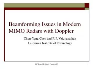
Beamforming Issues in Modern MIMO Radars with Doppler Chun-Yang Chen and P. P. Vaidyanathan California Institute of Technology DSP Group, EE, Caltech, Pasadena CA
Outline • Review of the MIMO radar • Spatial resolution. [D. W. Bliss and K. W. Forsythe, 03] • MIMO space-time adaptive processing (STAP) • Problem formulation • Clutter rank in MIMO STAP • Clutter subspace in MIMO STAP • Numerical example DSP Group, EE, Caltech, Pasadena CA
SIMO Radar Transmitter: M elements Receiver: N elements ej2p(ft-x/l) ej2p(ft-x/l) dR dT w1f(t) w0f(t) w2f(t) Number of received signals: N Transmitter emits coherent waveforms. DSP Group, EE, Caltech, Pasadena CA
MIMO Radar Transmitter: M elements Receiver: N elements ej2p(ft-x/l) ej2p(ft-x/l) dR dT … MF MF f0(t) f2(t) f1(t) … Matched filters extract theMorthogonal waveforms. Overall number of signals: NM Transmitter emits orthogonal waveforms. DSP Group, EE, Caltech, Pasadena CA
MIMO Radar (2) ej2p(ft-x/l) ej2p(ft-x/l) q q dR dT=NdR … MF MF f0(t) f2(t) f1(t) … Transmitter: M elements Receiver: N elements q The spacing dT is chosen as NdR, such that the virtual array is uniformly spaced. Virtual array: NM elements DSP Group, EE, Caltech, Pasadena CA
MIMO Radar (3) • The clutter resolution is the same as a receiving array with NM physical array elements. • A degree-of-freedom NMcan be created using only N+M physical array elements. [D. W. Bliss and K. W. Forsythe, 03] + = Virtual array: NM elements Transmitter : M elements Receiver: N elements DSP Group, EE, Caltech, Pasadena CA
Space-Time Adaptive Processing (STAP) The adaptive techniques for processing the data from airborne antenna arrays are called space-time adaptive processing (STAP). airborne radar v vsinqi qi The clutter Doppler frequencies depend on looking directions. The problem is non-separable in space-time. jammer target vt i-th clutter DSP Group, EE, Caltech, Pasadena CA
Formulation of MIMO STAP target target ej2p(ft-x/l) ej2p(ft-x/l) vt vt q q vsinq vsinq dR dT=NdR … MF MF f0(t) f2(t) f1(t) … Transmitter : M elements Receiver: N elements target noise NML clutter jammer NML x NML DSP Group, EE, Caltech, Pasadena CA
Clutter in MIMO Radar size: NML size: NMLxNML DSP Group, EE, Caltech, Pasadena CA
Clutter Rank in MIMO STAP: Integer Case Integer case:gandb are bothintegers. The set {n+gm+bl} has at most N+g(M-1)+b(L-1) distinct elements. Theorem: If g and b are integers, This result can be viewed as the MIMO extension of Brennan’s rule. DSP Group, EE, Caltech, Pasadena CA
Clutter Signals and Truncated Sinusoidal Functions ci is NML vector which consists of It can be viewed as a non-uniformly sampled version oftruncated sinusoidal signals. X 2W The “time-and-band limited” signals can be approximated by linear combination of prolate spheroidal wave functions. DSP Group, EE, Caltech, Pasadena CA
Prolate Spheroidal Wave Function (PSWF) • Prolate spheroidal wave functions (PSWF) are the solutions to the integral equation [van tree, 2001]. 0 X -W W in [0,X] Frequency window Time window • Only the first 2WX+1 eigenvalues are significant [D. Slepian, 1962]. • The “time-and-band limited” signals can be well approximated by the linear combination of the first 2WX+1 basis elements. DSP Group, EE, Caltech, Pasadena CA
PSWF Representation for Clutter Signals The “time-and-band limited” signals can be approximated by 2WX+1 PSWF basis elements. clutter rank in integer case DSP Group, EE, Caltech, Pasadena CA
PSWF Representation for Clutter Signals (2) non-uniformly sample U: NML x rc A: rc x rc • The PSWF yk(x)can be computed off-line • The vector uk can be obtained by sampling the PSWF. DSP Group, EE, Caltech, Pasadena CA
truncated sinusoidal Linear combination PSWF Non-uniformly sample Non-uniformly sample Linear combination i-th clutter signal Sampled PSWF Stack Stack Linear combination Sampled PSWF i-th clutter signal Clutter covariance matrix U:NML x rc A:rc x rc DSP Group, EE, Caltech, Pasadena CA
Numerical Example qkH Rcqk • The figure shows the clutter power in the orthonormalized basis elements. • The proposed method captures almost all the clutter power. • Parameters: Proposed method N=10 M=5 L=16 g=N=10 b=1.5 NML=800 N+g(M-1)+b(L-1)=72.5 Eigenvalues k DSP Group, EE, Caltech, Pasadena CA
Conclusion • The clutter subspace in MIMO radar is explored. • Clutter rank for integer/non-integer g and b. • Data-independent estimation of the clutter subspace. • Advantages of the proposed subspace estimation method. • It is data-independent. • It is accurate. • It can be computed off-line. DSP Group, EE, Caltech, Pasadena CA
Further and Future Work • Further work • The STAP method applying the subspace estimation is submitted to ICASSP 07. • Future work • In practice, some effects such as internal clutter motion (ICM) will change the clutter space. • Estimating the clutter subspace by using a combination of both the geometry and the data will be explored in the future. New method DSP Group, EE, Caltech, Pasadena CA
References [1] D. W. Bliss and K. W. Forsythe, “Multiple-input multiple-output (MIMO) radar and imaging: degrees of freedom and resolution,”Proc. 37th IEEE Asilomar Conf. on Signals, Systems, and Computers, pp. 54-59, Nov. 2003. [2] D. Slepian, and H. O. Pollak, "Prolate Spheroidal Wave Functions, Fourier Analysis and Uncertainty-III: the dimension of the space of essentially time-and-band-limited signals," Bell Syst. Tech. J., pp. 1295-1336, July 1962. [3] D. J. Rabideau and P. Parker, "Ubiquitous MIMO Multifunction Digital Array Radar," Proc. 37th IEEE Asilomar Conf. on Signals, Systems, and Computers, pp. 1057-1064, Nov. 2003. [4] N. A. Goodman and J.M. Stiles, "On Clutter Rank Observed by Arbitrary Arrays," accepted to IEEE Trans. on Signal Processing. DSP Group, EE, Caltech, Pasadena CA
Thank you DSP Group, EE, Caltech, Pasadena CA
Comparison of the Clutter Rank in MIMO and SIMO Radar > > < • The clutter rank is a smaller portionof the total dimension. • The MIMO radar receiver can null out the clutter subspace without affecting the SINR too much. DSP Group, EE, Caltech, Pasadena CA
Formulation of MIMO STAP (2) target target ej2p(ft-x/l) ej2p(ft-x/l) vt vt q q vsinq vsinq dR dT … MF MF f0(t) f2(t) f1(t) … Transmitter : M elements Receiver: N elements T: Radar pulse period DSP Group, EE, Caltech, Pasadena CA
Fully Adaptive STAP for MIMO Radar Solution: ^ • Difficulty: The size of Ry is NML which is often large. • The convergence of the fully adaptive STAP is slow. • The complexity is high. DSP Group, EE, Caltech, Pasadena CA
Clutter Subspace in MIMO STAP: Non-integer Case • Non-integer case: g and b not integers. • Basis need for representation of clutter steering vector ci. • Data independent basis is preferred. • Less computation • Faster convergence of STAP • We study the use of prolate spheroidal wave function (PSWF) for this. DSP Group, EE, Caltech, Pasadena CA
Extension to Arbitrary Array • This result can be extended to arbitrary array. XR,n is the location of the n-th receiving antenna. XT,m is the location of the m-th transmitting antenna. ui is the location of the i-th clutter. v is the speed of the radar station. DSP Group, EE, Caltech, Pasadena CA
ej2p(ft-x/l) dR … MF MF … Review of MIMO radar: Diversity approach • If the transmitting antennas are far enough, the received signals of each orthogonal waveforms becomes independent. [E. Fishler et al. 04] • This diversity can be used to improve target detection. Receiver: DSP Group, EE, Caltech, Pasadena CA
Prolate Spheroidal Wave Function (PSWF) (2) • By the maximum principle, this basis concentrates most of its energy on the band [-W, W] while maintaining the orthogonality. • Only the first 2WX+1 eigenvalues are significant [D. Slepian, 1962]. • The “time-and-band limited” signals can be well approximated by the linear combination of the first 2WX+1 basis elements. DSP Group, EE, Caltech, Pasadena CA
ej2p(ft-x/l) q dT=NdR f0(t) f2(t) f1(t) Transmitter : M elements Review of MIMO Radar: Degree-of-Freedom Approach • The clutter resolution is the same as a receiving array with NM physical array elements. • A degree-of-freedom NMcan be created using only N+M physical array elements. ej2p(ft-x/l) q + = dR … MF MF … Receiver: N elements q Virtual array: NM elements [D. W. Bliss and K. W. Forsythe, 03] DSP Group, EE, Caltech, Pasadena CA