Download
1 / 32
320 likes | 514 Vues
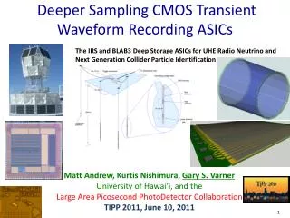
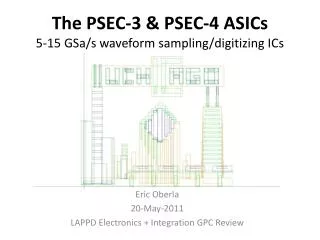
The PSEC-3 & PSEC-4 ASICs 5-15 GSa /s waveform sampling/digitizing ICs. Eric Oberla 20-May-2011 LAPPD Electronics + Integration GPC Review. O utline. PSEC series architecture review PSEC-3 --- testing results Submitted 11-Aug-2010, 40 parts received 16-Dec-2010

E N D
The PSEC-3 & PSEC-4 ASICs5-15 GSa/s waveform sampling/digitizing ICs Eric Oberla 20-May-2011 LAPPD Electronics + Integration GPC Review
Outline • PSEC series architecture review • PSEC-3 --- testing results • Submitted 11-Aug-2010, 40 parts received 16-Dec-2010 • PSEC-4 --- design & specifications • Submitted 9-May to MOSIS prototyping run • Plans LAPPD Electronics + Integration GPC review
PSEC series architecture • Waveform sampling using Switched Capacitor Array (SCA) • On-chip digitization up to 12 bits • Serial data readout • Region of interest readout capability • Self-triggering option • Designed to handle fast pulses (MCPs) • Sampling rate capability > 10GSa/s • Analog bandwidth > 1 GHz (challenge!) • Relatively short buffer size • Medium event-rate capability (~100 KHz) • IBM 130 nm CMOS process • Primary front-end chip for LAPPD MCPs LAPPD Electronics + Integration GPC review
PSEC-3 • Design targeted to fix issues with PSEC-2 • Still a prototyping version • 6 channels (2 test + 4 regular) • Test structures on chip • Testing underway December, 2010 4.3mm 4.0mm LAPPD Electronics + Integration GPC review
PSEC-3 specifications + results LAPPD Electronics + Integration GPC review
PSEC-3 die photo Open-cavity ceramic package LAPPD Electronics + Integration GPC review
PSEC-3 Evaluation Card (revA & B) LAPPD Electronics + Integration GPC review
PSEC-3 Evaluation Card (revA & B) USB 2.0 PSEC-3 • FPGA: Altera Cyclone III • Firmware developed at UC • USB readout software joint UH/UC effort LAPPD Electronics + Integration GPC review
PSEC-3 Sampling Rate • Sampling rates adjustable 2.5 – 17 GSa/s • Currently running at 10 GS/s, sampling lock with on-chip Delay-Locked Loop (DLL) • Good agreement with data +post-layout simulation LAPPD Electronics + Integration GPC review
PSEC-3 Sample Lock • Custom delay locked loop (DLL) design • Works great, except for some issues of de-locking when ADC is running • Attributed to drop in rail voltage/digital noise ---> issues addressed in PSEC-4 • Video: LAPPD Electronics + Integration GPC review
PSEC-3 ADC performance • Wilkinson ADC runs successfully to 2GHz (registers can be clocked to 3GHz) • Firmware has ADC running in ~10 bit mode: • 700 ns conversion (ramp ->0-1V) @ 1.6 GHz A/D conversion main power consumer in PSEC-3 – ~15 mW per channel (only ON during 700 ns ADC period) • Test structure (counter + ring oscillator) • Channel clock fan-out LAPPD Electronics + Integration GPC review
PSEC-3 Linearity & Dynamic Range • Channel 3Channel 4 • Fine DC scan + fit in linear region to get voltage/count conversion • Blue data points are raw data, without correction • Very linear in 450-900 mV range • Deviation < 400mV not fully understood (possibly due to comparator/buffer response or transistor Vthresh) LAPPD Electronics + Integration GPC review
PSEC-3 Linearity & Dynamic Range • Channel 3Channel 4 • Plot of fit residuals + cubic spline interpolation • Create look up table (LUT) to correct for ADC differential non-linearity • Currently, a software correction – work with Andrew Wong (UHawaii) • In linear region, ΔV < 1 LSB no (very few) missing codes LAPPD Electronics + Integration GPC review
PSEC-3 Noise NOISE CHANNELS 1-4 • Input noise ranges ~1-1.5 mV RMS • Dominant source of on-chip noise comes from analog buffers Issue addressed in PSEC-4 design LAPPD Electronics + Integration GPC review
PSEC-3 Noise <noise plots PSEC-3 simulation to compare> LAPPD Electronics + Integration GPC review
PSEC-3 AC performance • Analog Bandwidth • Timing Calibrations – save for Kurtis’ talk • 80 MHz sine wave @ 10GSa/s • (time-base not calibrated) LAPPD Electronics + Integration GPC review
PSEC-3 Analog Bandwidth • Quantify observation of attenuation along chip input line • -High series R of line (~160ohm) --- bad! • Histogram random phase sine waves – get amplitude along line Example (400MHz): Overlay sine data on 256 cells ------------> From histograms, amplitudes compared for 3 groups of cells: 1-5 61-65 141-145 LAPPD Electronics + Integration GPC review
More examples: (CW from top left 100MHz, 400 MHz, 1.2 GHz, 700MHz) LAPPD Electronics + Integration GPC review
PSEC-3 Analog Bandwidth HerveGrabas • Time-domain reflectrometery (TDR) of PSEC-3 input -> input line is much too capacitive ~11pF! (>> 2pF expected from post-layout extraction) • - suspected culprits: coupling to subtrate/top layer fill metal LAPPD Electronics + Integration GPC review
PSEC-3 Analog Bandwidth • Bandwidth highly dependent on location along input line: • First 5 cells have -3dB ~1.3 GHz (excluding 800MHz region) • Need to take more data to confirm trend 600-900 MHz • Reducing input line resistance should extend 1.3 GHz BW to later cells –> PSEC-4 • -- Careful layout to reduce input capacitance –> PSEC-4 LAPPD Electronics + Integration GPC review
PSEC-3 summary • PSEC-3 = working waveform sampling ASIC • Room for improvement: • ABW • Dynamic flip-flops proven difficult in ADC design • Overall readout speed • Fixes covered in careful redesign -> PSEC-4 • Still to characterize: • Timing calibrations -> timing measurements (resolution, jitter, etc.) • Temperature dependence • Up next: • Readout a detector! LAPPD Electronics + Integration GPC review
PSEC-4 • Design targeted to fix issues with PSEC-3 • 6 identical channels • each 256 samples deep • Submitted to MOSIS 9-May 2011 • 40 parts • May get a larger run via CERN MPW if necessary LAPPD Electronics + Integration GPC review
PSEC-4 specifications • Red = redesigned using what we learned from PSEC-3 • - Overall architecture the same: only small, necessary improvements made from PSEC-3 design (= confidence in design) LAPPD Electronics + Integration GPC review
PSEC-4 noise reduction • Comparator dominant noise source in redesign • Analog buffer removed • Replaced with effective buffering input stage to comparator (compact, low noise design) • In addition, noisy ramp analog buffer deemed unnecessary and removed • (after much simulation to convince ourselves) • Learned much regarding analog design from Eric Delagnes and others at the recent UChicago workshop <noise plot PSEC-4> LAPPD Electronics + Integration GPC review
PSEC-4 ABW improvement • Move input line to top layer metal (R ~ 5 ohms) • Factor of 30 reduction in resistance • PSEC-3 used MQ • PSEC-4 input line in microstrip configuration • PSEC-3 uses balanced, coplanar line • Change to unbalanced line -> less sensitive to distortion + easier to control impedance + less coupling to substrate! (=less parasitic capacitance) • ABW ~1.5 GHz seen by first cells in PSEC-3 should extend to all cells in PSEC-4 IBM 130nm 8RF-DM layer resistivity -----> HerveGrabas LAPPD Electronics + Integration GPC review
PSEC-4 ADC improvement • Change fast, dynamic flip flop + latch configuration in ADC counter with storage d-flip flop • Lose encoding capability > 2 GHz, but OK • Overall architecture unchanged • 12 bit +1 bit overcount with cell-addressed tri-state drivers on each for readout. • Simulation: Transfer Encoding @ 2 GHz Storing digital values (~10 us) Readout LAPPD Electronics + Integration GPC review
PSEC-3 & PSEC-4 plans • Parallel work on both chips • PSEC-3: • Continue characterizing PSEC-3 – work with Kurtis on time calibrations • Timing measurements! • Detector readout (later talk for details/opportunities) • PSEC-4: • Design of evaluation board (possibly using existing revA digital card) • Much of PSEC-3 firmware will transfer • Characterization (expect chip ~August) • PSEC-4 is baseline ASIC for LAPPD readout. • PSEC-3 is working 4-channel prototype and will be used extensively in meantime LAPPD Electronics + Integration GPC review
BACKUP LAPPD Electronics + Integration GPC review
PSEC architecture – timing generation Phase Compa-rator Charge pump • 256 Delay units – starved current inverter chain -----------> • Sampling window strobe (8x delay) sent to each channel’s SCA • On chip phase comparator + charge pump for sample lock LAPPD Electronics + Integration GPC review
PSEC architecture -- sampling LAPPD Electronics + Integration GPC review
PSEC architecture – ADC + readout Level from sampling cell Comp. Clk enable Read enable fast 12 bit register 2-2.5 GHz Ring Oscillator 12 bit data bus Ramping circuit Readout shift register/ one-shot: “Token” … 256x … LAPPD Electronics + Integration GPC review
Bandwidth with gain=2 amplifier • Comments: • On-board amplifier (channel 4) unstable with unity gain – works with gain=2 • -3dB BW ~700 MHz for first cells • Amplifier = THS4304 LAPPD Electronics + Integration GPC review