Download

1 / 32
350 likes | 1.35k Vues
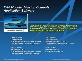
Lauren E. Clark Chief Engineer F-16 Modular Mission Computer Software Lockheed Martin Aeronautics Company Terry Ruthruff Staff Specialist Software Engineering Core Lockheed Martin Aeronautics Company Allan Kennedy Managing Director Kennedy Carter Limited Bary D. Hogan Methodology Lead

E N D
Lauren E. Clark Chief Engineer F-16 Modular Mission Computer Software Lockheed Martin Aeronautics Company Terry Ruthruff Staff Specialist Software Engineering Core Lockheed Martin Aeronautics Company Allan Kennedy Managing Director Kennedy Carter Limited Bary D. Hogan Methodology Lead F-16 Modular Mission Computer Software Lockheed Martin Aeronautics Company F-16 Modular Mission ComputerApplication Software Achieving Cross-Platform Compatibility with Increased Productivity and Quality using the OMG’s Model Driven Architecture
Agenda • The Platform • Cross-Platform Compatibility: The Goal • The eXecutable MDA Approach: • eXecutable UML Modeling • Platform Specific Mapping (Design Tagging) • Automatic Code Generation • Benefits derived from using eXecutable MDA
Basic Software Components Software Application Software Application Software: • High-level software that is unique to the application(s) for which the embedded computer (i.e. subsystem) exists • 80-90% of the total software (in terms of long-term development cost) Application Software Interface Software Execution Platform Software Execution Platform: • Low-level software, the purpose of which is to provide services that allow the Application Software to run on the hardware Hardware
Software Execution Platform Application Software Application Software Interface Software Execution Platform Software Architecture Software Execution Platform: • Low-level software, the purpose of which is to provide services that allow the Application Software to run on the hardware Device Drivers Operating System Board Support Package / BIT Hardware
Software Architecture Software Architecture: • Low-level software providing the framework within which the Application Software executes • Provides execution control, data / message management, error handling, and various support services to the Application Software • Assumes a particular Application Software language • Unique to the hardware; but, since it must support all requirements levied by the Application Software, is not delivered with the hardware Application Software Application Software Interface Software Execution Platform Software Architecture Software Architecture Device Drivers Operating System Board Support Package / BIT Hardware
Application Software Interface Application Software Application Software Interface: • The boundary between the Application Software and the Software Execution Platform • The specified methods by which the Application Software can make requests and use the services of the Software Execution Platform and the Software Execution Platform can provide its services to the Application Software • This interface is specified by the Software Execution Platform Application Software Interface Application Software Interface Software Execution Platform Software Architecture Device Drivers Operating System Board Support Package / BIT Hardware
Cross-Platform Compatibility: The Usual Approach Maintain a constant Application Software Interface Application Software Application Software Portable Hold Constant Application Software Interface Application Software Interface Software Architecture Software Architecture Device Drivers Operating System Device Drivers Operating System Board Support Package / BIT Board Support Package / BIT Hardware Hardware Platform #1 Hardware Platform #2
Cross-Platform Compatibility Issues Application Software Can a constant Application Software Interface always be maintained? Consider… • What if the language or operating system becomes obsolete? • What if it is necessary to port even a part of the Application Software to a legacy platform not having the resources to support the newer Software Execution Platforms? Application Software Interface Software Architecture Device Drivers Operating System Board Support Package / BIT Hardware Platform
Cross-Platform Compatibility Issues Application Software Even if it were possible, would one always want to maintain a constant Application Software Interface? Consider… • What if hardware or Software Execution Platform changes could provide more Application Software capability, but only by means of changing the Application Software Interface? Application Software Interface Software Architecture Device Drivers Operating System Board Support Package / BIT Hardware Platform
Cross-Platform Compatibility: The Goal Application Software The goal should be to provide cross-platform compatibility of Application Software despite any Implementation, or platform specific, changes: that is, changes to the Hardware Platform, the Software Execution Platform, or the Application Software Interface Application Software Interface Software Architecture Device Drivers Operating System Board Support Package / BIT Hardware Platform
eXecutable MDA: Application Software Development The eXecutable MDA Approach as supported by KC’s iUML and iCCG Requirements Definition eXecutable UML Modeling Platform Specific Mapping (Design Tagging) Application Software Interface Definition Automatic Code Generation Integration & Test
eXecutable UML Modeling: Domain Model Domain Model (Package Diagram): • The software application space is partitioned into multiple platform independent domain models • Mappings between the domains are defined as contracts for required and provided services
eXecutable UML Modeling: Class Diagrams Class Diagrams: • Within each platform independent domain model, conceptual entities are modeled first: classes,attributes, and associations are abstracted • Behavior, though considered, is not modeled explicitly in this view
eXecutable UML Modeling: State Charts State Charts: • Behavior is formalized during state modeling • Class lifecycles are modeled using signal-driven state machines • Class operations are defined
eXecutable UML Modeling: Action Language Action Specification Language: • State actions and class operations are specified using Kennedy Carter’s Action Specification Language (ASL) • ASL is a higher order and much simpler language than a typical high order language (e.g. C++) • ASL deals with UML concepts, not implementation concepts • ASL was a major influence on the newly adopted Precise Action Semantics for the UML
eXecutable UML Modeling: Simulation Simulation: • Since a precise Action Specification Language is used, models are executable and therefore may be simulated • Simulation features resemble those of a high order language debugger • Models may be validated long before they are implemented
Design Tagging: Specifying the PIM to PSM Mapping ... Source Code Files xUML Models ... ... ... ... ... Design Tags • Class Allocation • Program Allocation • Max Instance Count • Event Rate • Event Queue • Throw Away • Initialization • Source Type • Subtype of • etc. Software Execution Platform Specific Language Specific Defines Automatic Code Generator Application Software Interface Definition
Design Tagging: Specifying the PIM to PSM Mapping Design Tagging: • Design tag values represent implementation-specific design decisions • Design tagging is applied to, but not embedded in, the xUML models (tags and tag values may be included or excluded) • Code Generator assumes the most standard implementation, such that only exceptions must be tagged
Automatic Code Generation: 3 Levels of Models Model of Platform Model of xUML ... Model of Application ... ... ... ... ... Level 3 Developed by Program Level 2 Supplied by Kennedy Carter Level 1 Developed by Program Implementation Elements: (e.g. Procedure, Array, Program, Event Queue, etc.) xUML Elements: (e.g. Class, Attribute, Association, Tag, etc.) Application Elements: (e.g. Aircraft, Missile, Target, etc.)
Automatic Code Generation: Level 2 - Simulation Code Level 2 Supplied by Kennedy Carter Model of xUML Level 1 Developed by Program Model of Application ... ... xUML Elements: (e.g. Class, Attribute, Association, Tag, etc.) ... Application Elements: (e.g. Aircraft, Missile, Target, etc.) ... When we say that “xUML models are executable” we mean that “executable code can be automatically generated from them” Code Generation: Generation of Simulation Code for Development Platform (e.g. UNIX C Code) Step 1: Populate instances of xUML Metamodel with Model of Application
Automatic Code Generation: Level 3 - Target Code Level 3 Developed by Program Model of Platform Level 2 Supplied by Kennedy Carter Model of xUML Level 1 Developed by Program ... Model of Application ... Implementation Elements: (e.g. Procedure, Array, Program, Event Queue, etc.) ... ... xUML Elements: (e.g. Class, Attribute, Association, Tag, etc.) ... Application Elements: (e.g. Aircraft, Missile, Target, etc.) ... Code Generation: Generation of Source Code for Target (Embedded) Platform (e.g. Ada/C++ Code) Step 2: Populate instances of Model of Implementation with populated xUML Metamodel instances Step 1: Populate instances of xUML Metamodel with Model of Application
Automatic Code Generation: The Code Generator Level 3 Developed by Program Model of Platform Level 2 Supplied by Kennedy Carter Model of xUML Level 1 Developed by Program ... Model of Application ... Implementation Elements: (e.g. Procedure, Array, Program, Event Queue, etc.) ... ... xUML Elements: (e.g. Class, Attribute, Association, Tag etc.) ... Application Elements: (e.g. Aircraft, Missile, Target, etc.) ... The Code Generator Generated Source Code for Target Platform The Code Generator includes all implementation-dependent details (those dependent upon the Application Software Interface – specific to the Hardware, the Software Execution Platform, the Implementation Language)
Automatic Code Generation: Code Generator Development Configurable Code Generator: • Code Generator is developed using the same eXecutable MDA strategy • Kennedy Carter supplies a set of xUML models (known as the Configurable Code Generator) that serve as a generic translation framework
Automatic Code Generation: Code Generator Development Code Generator Development: • The Configurable Code Generator (iCCG) may be adapted to the meet the requirements of any Platform Specific Implementation (i.e. of any Application Software Interface) • Code Generator and Application Software develop- ment may be performed concurrently
Automatic Code Generation: Summary Automatic Code Generation • Automatic code generation is simply an extension of the code generation technique used for simulation of the eXecutable UML models on the development platform, this extension being for the target (embedded) platform • The code generator is developed within the same environment as the application software using the same eXecutable MDA strategy • Development cost: 1-2 architects • Nearly all implementation-specific design tasks (all but the design decisions represented by design tag values) are performed by the code generator, not the software developers
Portable Application Software Products eXecutable UML Models Program Specific Mapping (Design Tag Values) Application Software Interface Automatic Code Generator Source Code The Portable Products (and therefore the Configured Products to be placed in an Enterprise-Level Software Reuse Library) eXecutable UML Models Program Specific Mapping (Design Tag Values) Application Software Interface Automatic Code Generator Source Code
Advantages of the eXecutable MDA Approach Increased Quality • The majority of software developers are isolated from implementation details, allowing them to focus on a thorough analysis of the application space • Maintenance of the application source code is eliminated, while maintenance of the xUML models is ensured • Defect injection (and the resulting rework) is reduced by automating the software phase in which most defects are injected • On a typical program, after Requirements Definition approximately 2/3 of the defects are injected during implementation (coding)
Advantages of the eXecutable MDA Approach Increased Productivity • Rework is reduced • Early validation through simulation reduces rework • Increase in eXecutable UML modeling span time is more than offset by decrease in Integration & Test span time • Higher quality implementation (due to automation) reduces rework • Software development span time is reduced by automating the implementation phase • Application Software development schedule is reduced by at least 20% • The code generator, not each software developer, performs the majority of implementation-specific design tasks • 40-60% of physical source code
Advantages of the eXecutable MDA Approach Cross-Platform Compatibility • One Application Software xUML Model database may be reused (as is) on any platform for which a mapping is defined (ie: a code generator is developed) • xUML models are compatible with any hardware platform, any Software Execution Platform, and any Application Software Interface • xUML models are compatible with any implementation language The Goal of Cross-Platform Compatibility of Application Software is Attainable with the eXecutable MDA Approach
eXecutable MDA: Summary of Key Themes • The platform is an xUML virtual machine (but platform independent models can’t assume anything about the interface) • To validate PIMS as long-life assets we need eXecutable UML • eXecutable UML needs an action language, not a 3GL • Systems are integrated from multiple platform independent models • PIMS offer contracts for required and provided services • 100% code generation is essential to make MDA a lightweight process • But don’t worry – its just another type of expert knowledge to formalise in xUML • It works • It makes sense • Its proven
Projects Using eXecutable MDA with KC’s Tools • BAE Systems: Stingray torpedo MLU • TRW Automotive: vehicle stability system • Siemens Metering: ‘intelligent’ gas meter • Thales: Nimrod MR4 crew trainers • GD Government Systems: ATM Switch for US Army • Royal Netherlands Navy: combat systems • Nortel Networks: Passport Voice Gateway • GCHQ: classified distributed application • UK NHS: patient control of access to medical records
Contact Information Lauren E. Clark Chief Engineer F-16 Modular Mission Computer Software Lockheed Martin Aeronautics Company Lauren.E.Clark@lmco.com (817) 763-2748 Terry Ruthruff Staff Specialist Software Engineering Core Lockheed Martin Aeronautics Company Terry.Ruthruff@lmco.com (817) 763-3525 Bary.D.Hogan@lmco.com (817) 763-2620 Bary D. Hogan Methodology Lead F-16 Modular Mission Computer Software Lockheed Martin Aeronautics Company allan.kennedy@kc.com (+44) 1483 226 180 Allan Kennedy Managing Director Kennedy Carter Limited