Download
1 / 24
240 likes | 1.14k Vues
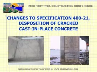
CHANGES TO SPECIFICATION 400-21, DISPOSITION OF CRACKED CAST-IN-PLACE CONCRETE 400-21.2, Investigation, Documentation and Monitoring The Engineer will inspect for cracks when the following occurs: As soon as surfaces are fully visible after casting

E N D
CHANGES TO SPECIFICATION 400-21, DISPOSITION OF CRACKEDCAST-IN-PLACE CONCRETE FLORIDA DEPARTMENT OF TRANSPORTATION – STATE CONSTRUCTION OFFICE
400-21.2, Investigation, Documentation and Monitoring • The Engineer will inspect for cracks when the following occurs: • As soon as surfaces are fully visible after casting • After the component has full dead load applied • After the bridge is carrying full unrestricted traffic • If Cracks are Found, the Engineer Will Produce a Crack Map • Contractor will provide the Engineer access to cracked areas • Engineer will monitor crack growth and set the monitoring interval FLORIDA DEPARTMENT OF TRANSPORTATION – STATE CONSTRUCTION OFFICE
400-21.3, Classification of Cracks • The Engineer will classify cracks as Structural or Nonstructural • Structural: extend beyond the depth of outermost reinforcing steel and are caused by excessive load, inadequate support conditions during casting, or uncontrolled temperature gradients • Nonstructural: shallow depth cracks that form during curing and do not extend beyond the first layer of rebars • The Contractor will be given the opportunity to review and comment on the Engineer’s classification of cracks but the Engineer makes the final determination FLORIDA DEPARTMENT OF TRANSPORTATION – STATE CONSTRUCTION OFFICE
400-21.4, Resolution • Repair nonstructural cracks according to Specification Tables 1 or 2 • Table 1: substructures and superstructures other then decks • Table identifies 3 environmental zones based on their proximity to mean high water which is different and more accurate than the old spec. • Accounts for the number of cracks for a given surface area by requiring a higher level of repair for a greater number of cracks which is different and more effective than the old spec. • Table 2:bridge decks • Table identifies 2 environmental zones based on mean high water • Accounts for the number of cracks • Allows the use of Methacrylate as a repair method FLORIDA DEPARTMENT OF TRANSPORTATION – STATE CONSTRUCTION OFFICE
FLORIDA DEPARTMENT OF TRANSPORTATION – STATE CONSTRUCTION OFFICE
FLORIDA DEPARTMENT OF TRANSPORTATION – STATE CONSTRUCTION OFFICE
400-21.4, Resolution • Disposition of structural cracks requires a structural evaluation and written recommendations by a Specialty Engineer • The Engineer will make the final determination of whether the concrete is to be repaired or replaced • Repair methods must be approved by the Engineer before work begins FLORIDA DEPARTMENT OF TRANSPORTATION – STATE CONSTRUCTION OFFICE
How to use Table 1 and 2 1) TOTAL CRACK AREA PER LOT - Calculate the average crack width by taking 3 measurements of width for each crack and averaging them. Then multiply the average crack width by the length of the crack which results in the area of an individual crack. Finally, add together the areas of all the individual cracks within a LOT to get the total crack area per LOT. 2) TOTAL CONCRETE SURFACE AREA PER LOT - Use 100 square feet (sf) [14,400 square inches (si)] for substructure LOTs unless the surface area is less than 100 sf in which case compute the LOT size based on the existing geometry of the component or Use 400 sf (57,600 si) for decksunless the area is less, then compute it. FLORIDA DEPARTMENT OF TRANSPORTATION – STATE CONSTRUCTION OFFICE
How to use Table 1 and 2 3) PERCENT OF TOTAL CONCRETE SURFACE AREA THAT IS CRACKED -Divide Step (1) by Step (2) then multiply the result by 100, for EXAMPLE: Crack 1-Average crack width=10 mils (0.01”) Crack 2-Average crack width=4 mils (0.004”) Crack length = 8’ (96”) Crack length = 3’ (36” ) Crack area = 0.01” X 96” = 0.96 si Crack area = 0.004” X 36” = 0.144 si Total crack Area = Sum of all individual crack areas = 0.96 + 0.144 = 1.104 si Average crack width of LOT = (0.01” + 0.004”) / 2 = 0.007” % Total Surface Area That Is Cracked = Total Crack Area per LOT X 100 Total Concrete Surface area per LOT = (1.104 si / 14,400 si) X 100 = 0.008 % (rounded off) FLORIDA DEPARTMENT OF TRANSPORTATION – STATE CONSTRUCTION OFFICE
0.008 % 0.007” FLORIDA DEPARTMENT OF TRANSPORTATION – STATE CONSTRUCTION OFFICE
FLORIDA DEPARTMENT OF TRANSPORTATION – STATE CONSTRUCTION OFFICE
THAT’S ALL FOLKS FLORIDA DEPARTMENT OF TRANSPORTATION – STATE CONSTRUCTION OFFICE
REVISIONS TO SPECIFICATION 400-5.7, STAY-IN-PLACE (SIP)METAL FORMS, PROVIDING FOR THE USE OF POLYMER LAMINATED COMPONENTS FLORIDA DEPARTMENT OF TRANSPORTATION – STATE CONSTRUCTION OFFICE
400-5.7.1, General • There will now be four types of SIP forms: (1) galvanized with no polymer coating, (2) galvanized with polymer coating on the form top only, (3) galvanized with polymer coating on the form bottom only (4) galvanized with polymer coating on both sides of the form • Type 1 - Galvanized metal forms currently in use that can only be used in slightly aggressive environments without Styrofoam in flutes and which can be assembled by welding • Type 2 – Same as Type 1 but with a polymer laminated coating on the top surface that protects the panels and other components from corrosion due to water accumulation in flutes when Styrofoam is used as a replacement for concrete in a slightly aggressive environment FLORIDA DEPARTMENT OF TRANSPORTATION – STATE CONSTRUCTION OFFICE
400-5.7.1, General • Type 3 - Same as Type 1 but with a polymer laminated coating on the bottom surface that protects the panels and other components from corrosion for use in moderately and extremely aggressive environments and without use of Styrofoam in the flutes • Type 4 - Same as Type 3 but with a polymer laminated coating on the top surface that allows Styrofoam to be used as a replacement for concrete in form flutes • For Type 2, 3 and 4 forms, the support angle to beam attachment clip connections cannot be welded but instead must be made with screws, bolts or clips. FLORIDA DEPARTMENT OF TRANSPORTATION – STATE CONSTRUCTION OFFICE
COATING APPLICATION PROCESSSIP Components, in the form of sheet steel, are galvanized as always then the surface of the galvanizing is chemically treated in order to insure that the polymer laminate adheres to it properly. The laminate is then applied.This all takes place prior to cold forming; however, the laminate is flexible and strong enough to withstand cold forming without a reduction in performance or durability. FLORIDA DEPARTMENT OF TRANSPORTATION – STATE CONSTRUCTION OFFICE
400-5.7.3, Materials • The bottom and/or top surface of panels will be protected by a polymer laminated coating that meets specific materials requirements in addition to the standard galvanized coating • Sheared uncoated edges of form system components (panels, angles, etc.) will be coated with 2 coats of shop applied material that is equivalent to the polymer laminate • The polymer film shall have a nominal thickness of 12 mils as manufactured and a minimum thickness of 10 mils after lamination to the steel sheet and shall be sufficiently flexible to withstand the forming process FLORIDA DEPARTMENT OF TRANSPORTATION – STATE CONSTRUCTION OFFICE
400-5.7.3, Materials Cont. • Polymer materials must meet specific UV resistance standards in order to prevent excessive damage from sun exposure during the life of the bridge • Screws used in fastening, require a corrosion resistant coating or plating that will not have an adverse effect on the system due to the contact of dissimilar metals • A written certification from the manufacturer stating the product meets the requirements of this specification must be provided with the forms at the time of delivery to the job site FLORIDA DEPARTMENT OF TRANSPORTATION – STATE CONSTRUCTION OFFICE
400-5.7.4, Construction • If the polymer laminate coating is damaged, it must be repaired with liquid polymer coating that is similar and compatible with respect to durability, adhesion and appearance and that is furnished by the stay-in-place form manufacturer • The coating may be applied with a brush in accordance with manufacturer’s written specifications • The repair coating must be at least 2 coats and have a total finished thickness of not less than 6 mils • Coating that is damaged as a result of panel removal to allow for inspection of defective concrete, must be repaired with liquid polymer FLORIDA DEPARTMENT OF TRANSPORTATION – STATE CONSTRUCTION OFFICE
ASSEMBLY DETAILSCross Section FLORIDA DEPARTMENT OF TRANSPORTATION – STATE CONSTRUCTION OFFICE
ASSEMBLY DETAILSSection A-A View FLORIDA DEPARTMENT OF TRANSPORTATION – STATE CONSTRUCTION OFFICE
PERMANENT FLORIDA PROJECTS WHERE POLYMER LAMINATE HAS BEEN USED (each was approved as a test project) • TROUT RIVER BRIDGE REPLACEMENT, I-95 Jacksonville – First use in Florida in order to save forming costs and reduce overall project duration. Environment was over brackish water. The Contractor was given the option of choosing the coated forms after letting with no cost adjustment. • ESCAMBIA BAY BRIDGE REPLACEMENT, 1-10 Pensacola – Used to reduce project duration on an accelerated schedule hurricane recovery project. Environment was over brackish water. The Contractor was given the option of choosing the coated forms after letting with no cost adjustment. • JEWFISH CREEK BRIDGE REPLACEMENT, US 1 Key Largo – Used to save forming costs and to reduce project duration. Full salt water environment and panels coated on both sides. Contractor option with no cost adjustment. FLORIDA DEPARTMENT OF TRANSPORTATION – STATE CONSTRUCTION OFFICE
FUTURE CONSIDERATIONS • Styrofoam Flute Inserts and Sheet Metal Flute Covers • These will be allowed for form systems having polymer laminated coatings on the side that is in direct contact with concrete • These may be allowed for form systems that are not polymer coated based on planned investigation of performance in other states where they are currently allowed as well as possible lab tests by FDOT • Possible advantages of using Styrofoam or covers due to reduced weight of concrete in flutes – Equivalent concrete savings of deck concrete ranges from 1/2” to 1” • Reduced concrete quantities, costs and placement duration • Reduction in SIP form panel costs • Reduction in girder/beam costs • Reduction in substructure costs • Disadvantages of using Styrofoam or covers • Added material costs for polymer coating, Styrofoam/covers, mechanical fasteners (Type 2 forms only), touch up coating and beam clips • Added labor costs for Styrofoam/cover placement and coating touch ups • Added labor costs associated with using mechanical fasteners instead of being able to tack weld support angles to beam clips (Type 2 forms only) FLORIDA DEPARTMENT OF TRANSPORTATION – STATE CONSTRUCTION OFFICE
THAT’S ALL FOLKS FLORIDA DEPARTMENT OF TRANSPORTATION – STATE CONSTRUCTION OFFICE