Download
1 / 1
10 likes | 156 Vues
The hydrostatic test apparatus, essential for testing electrical enclosures under high pressure, is being redesigned to integrate automated control via a digital interface. This innovative approach will optimize pressure, ramp rates, and hold times, allowing technicians to monitor tests and record results seamlessly. The new system must maintain a maximum pressure of 10,000 PSI, require minimal maintenance, and interface effectively with existing pumps. Our design, validated through FEA analysis, overcomes challenges in valve actuation by utilizing a ball screw mechanism, ensuring both power and precision.

E N D
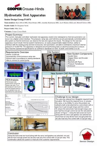
Hydrostatic Test Apparatus Senior Design Group P14474 Team members: Kyle Abbott (ME), Brian Benner (ME), Anushka Kalicharan (ME), Jacob Manley (EE/Lead), Mitchell Sedore (ME) Faculty Guide: Dr. Benjamin Varela Project Guide: Mike Zona Customer: Cooper Crouse-Hinds Project Summary: The current, manually controlled, hydrostatic test apparatus needs to be redesigned so that test automation can occur via a digital control interface. The pressure, ramp rate, and hold time are all automatically controlled within the system so that the technician can observe the test and capture the results. The design for the new test apparatus must include minimal system maintenance, an easily programmable digital interface, ability to interface with the existing pump and test enclosures, test automation, and able to withstand a maximum internal pressure of 10,000 PSI. The apparatus is designed around performing tests on electrical enclosures to ensure they meet the operational specifications as outlined in standards UL1203, UL2225, and CSA22.2 no.30. Old System Requirements Overview -Deliver 10,000 psi -Automatically control pressure ramp rate -Perform test in accordance to testing standards -Able to connect to current pump New System Components -Needle Valve -Stepper Motor and Encoder -Ballscrew -Manifold with Pipes -Pressure Transducers -Enclosure New System CAD Rendering FEA Analysis FEA Analysis was performed to ensure the design was safe. From the analysis it was found that the stresses were at an acceptable level and well below the yield stress Challenge to our design: The valve we ordered from Swagelok required linear actuation. We found the required force, to actuate the valve, to be 200lbs.To solve this problem we utilized a ball screw attached to a servomotor with a gear box to get enough torque and fine control To ensure the servomotor had enough torque and we had fine enough control we ran the calculations shown in Figure 1. Using the ball screw we found along with the servo and gearbox we selected we found that not only did we have enough power but we also had very fine control with 3.3 psi per step. Figure 1 Conclusion Using the ball screw we found along with the servo and gearbox we selected, not only did we have enough power but we also had very fine control with 3.3 psi per step. This combination allows the system to meet all of the customer requirements