Download
1 / 67
670 likes | 765 Vues
Explore the fundamental aspects of Internet Protocol (IP) addressing, including address hierarchy, address classes, subnetting, and classless addressing. Learn how IP addresses are assigned and the principles behind routing efficiency in networking.

E N D
Fall 2005Brief Coverage of TopicsIP, ARP, UDP, TCP, and DNS Qutaibah Malluhi CSE Department Qatar University
IP Addressing Qutaibah Malluhi CSE Department Qatar University
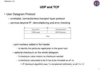
Internet Protocol (IP) • Protocol at Layer 3 • Fundamental in suite • Defines • Internet addressing • Internet packet (datagram) format • Internet routing
IP Address • Each host is assigned a 32-bit number • Called the IP address or Internet address • Unique across entire internet (virtual network) • Only understood by software (not related to hardware address) • Identifies a connection between a computer and the network. • Does not identify a specific computer • A computer with multiple network connections (e.g., a router) must be assigned one IP address for each connection.
Address Hierarchy • Divided into two parts • Prefix identifies network (Net ID) • Suffix identifies host within the network (Host ID) • Global authority (see ARIN.NET and IANA.NET) assigns unique prefix to network • Local administrator assigns unique suffix within this network to host • Address format makes routing efficient Net ID Host ID
IP Address Format Net ID Host ID 32 bits Net ID Host ID • IP designers chose 32-bit addresses • Allocate some bits for prefix, some for suffix • Large prefix, small suffix - many networks, few hosts per network • Small prefix, large suffix - few networks, many hosts per network • Because of variety of technologies, need to allow for both large and small networks
Classes of Addresses • Multiple address formats • Allow both large and small prefixes • Each format is called an address class • Class of an address is identified by first four bits • First byte values: • 1-127 Class A -- 128-191 Class B -- 192-223 Class C -- 224-239 Class D
Dotted Notation • Dotted decimal notation is a convention for representing 32-bit internet addresses in decimal • Represents each octet in decimal separated by dots • Note: Not the same as names like www.google.com.
QU IP Addressing • QU has a single Class B network: 143.132.0.0 • All fixed IP address hosts (usually servers) at JSU have 143.132 prefix: • 143.132.1.13 – www.jsums.edu same as ccaix.jsums.edu • 143.132.6.62 – programmer • 143.132.1.1 – jsugw (JSU’s Internet router) • 143.132.8.90 – redhat3 • JSU also uses an internal network on which IP addresses are assigned dynamically. For example, • 10.30.0.0 • 10.40.0.0
Addressing Example • Select address class for each network depending on expected number of hosts • Assign host suffixes to form internet addresses for all hosts
Illustration Of Router Addresses • Address prefix identifies network • Need one router address per connection
Subnet And Classless Addressing • Solution: • Subnet addressing • Allows network to be divided into multiple sub-networks. Subnetting • Classless addressing • In addition to allowing subnetting, allows multiple classful addresses to be grouped for a single network. ClasslessAddressing • Inefficient use of addresses • Network should choose one of the three possible sizes (classes) • E.g., many small companies have < 16 computers. Each would get a class C (255) addresses with many unused addresses. • Basic Idea: • Allow boundary between prefix and suffix to occur on arbitrary bit boundary • Require auxiliary information to identify boundary
Address Mask • Accompanies IP address • 32 bit binary value • Specifies Net ID-Host ID (prefix-suffix) address boundary • 1 bits cover Net ID • 0 bits cover Host ID • Example: class B mask is 255.255.0.0 • Network address can easily be found from a host address by “AND”ing the mask with the address Net Address = “Dest. Address” & “Mask”
Address Mask Examples • What is the address mask for a class A, B, or C networks? • Class A: 11111111.00000000.00000000.00000000 = 255.0.0.0 • Class B: 11111111.11111111.00000000.00000000 = 255.255.0.0 • Class C: 11111111.11111111.11111111.00000000 = 255.255.255.0 • What is the address mask if host ID is 7 bits? • 11111111.11111111.11111111.10000000 = 255.255.255.128 • What is the address mask needed if we need 2000 hosts on the network? • 11 host bits are needed • 11111111.11111111.11111000.00000000 = 255.255.248.0
Subnet Addressing • Goal: extend address space • Works within a site • Technique • Assign single network prefix to site • Divide suffix into two parts: network at site and host • Example: • Divide class C address (< 255 addresses) into 8 subnets with < 31 each • 3 bits of original suffix are used to specify the network at the current site and 5 bits for the host ID. • The total prefix size is 24+3 = 27 • Network mask for each subnet is 255.255.255.224
Example 2 of Subnet Addressing • Single Class B number such as 128.10.0.0 assigned to site • Site chooses subnet boundary such as 24 bits • Routers and hosts configured with corresponding subnet mask M = 255.255.255.0 • Given destination address, D, extract prefix with “logical and” operation D & M
How Does It Work? • Route locally to the subnet • Group physically close nets to share a single Net ID • Subnetting is not visible to the outside world. An organization decides internally how to implement subnetting • You only need to reach any subnet (router) inside the network (that contains the host)
Example • Main Network IP number is 128.96.0.0 • Net mask is 255.255.0.0 • Create three subnets: • One which less than 250 hosts • Two with less than 125 hosts each • What are the addresses and subnet masks of these subnets?
Subnet Example 128.96.34.15 128.96.34.19 128.96.34.139 128.96.34.151 128.96.33.14 128.96.33.21 128.96.34.1 128.96.34.130 128.96.34.129 128.96.33.1 Mask: 255.255.255.128 Subnet ID: 128.96.34.0 Mask: 255.255.255.128 Subnet ID: 128.96.34.128 Mask: 255.255.255.0 Subnet ID: 128.96.33.0 A B C D E F N1 N2 N3 R1 R2 • How many host-bits are needed for each subnet • 125 hosts 7 bits (N1 and N2) • 250 hosts 8 bits (N3) Internet • Specify Netmasks • Assign net IDs to subnets • Assign proper host IDs
Subnetting Steps • Find how many host-bits are needed for each subnet • E.g. < 125 • Accordingly, specify the net mask for each subnet • E.g. 7 bits • Assign proper Net IDs (by assigning subnet IDs) • The subnet IDs bits are the bits which correspond to a 1 in the net mask but not part of the original class net ID. • Notice that you do not have control on assigning all the bits. The first Net ID bits (e.g. 143.132 for JSU) are the bits reserved by the organization for the main network from the central authority. • Assign proper Host IP addresses • All hosts on the same subnets should have the same subnet ID • You need only assign host IDs field (since net ID is already specified) • Host ID bits are the bits which correspond to a zero in the net mask
Subnet Routing Table Routing table for R2 in the example:
A Subnetting Example • Packet to H1, 128.96.34.15 AND 255.255.255.128 = 128.96.34.0 => left router (R1)
Classless Addressing • Known as Classless Inter-Domain Routing (CIDR) • Goal: extend address space • Works throughout Internet • Accommodates • Original classful addresses • Subnet addresses • Allows multiple networks to be grouped into a single network address • Will not Cover it
The Internet Protocol Summary Qutaibah Malluhi CSE Department Qatar University
IP Connectionless Service • End-to-end delivery service is connectionless • Universal addressing • Data delivered in packets (frames), each with a header • Combines heterogeneous physical networks into single, virtual network • Routers (or gateways) forward between physical networks • Transport protocols use this connectionless service to provide • Connectionless data delivery (UDP) , or • Connection-oriented data delivery (TCP)
Virtual IP Packets Header Data IP datagram • Abstraction created and understood only by software • Because IP can connect heterogeneous networks • Must define a hardware-independent packet format • O/W, router can not relay a copy of a frame to across different networks • Formally called IP datagram • Datagrams have variable size • Header • Contains sender and destination addresses • 20 octets but may have options • Payload • Variable size up to 64K • No minimum size • Data is usually much larger than header
Datagram Forwarding • Header contains all information needed to deliver datagram to destination • Destination address • Source address • Identifier • Other delivery information • Router examines header of each datagram and forwards datagram along path to destination
Forwarding Uses a Routing Table • Contains list of destination networks and next hop for each destination • Like WAN forwarding, • Table-driven • Entry specifies next hop • Unlike WAN forwarding, • Uses IP addresses • Next-hop is router or destination
Example Of An IP Routing Table • Table (b) is for center router in part (a)
Routing Table Fields • Destination: • stored as network address • Next hop: • stored as IP address of router • Address mask: • defines how many bits of destination address are in prefix • Prefix defines how much of address used to identify network • E.g., class A mask is 255.0.0.0 • Used for subnetting
Datagram Forwarding Algorithm • Given a datagram • Extract destination address field, D • Look up prefix of D in routing table • Find destination entry in the table such that ((Mask[i] & D) == Dest[i]) forward to NextHop[i] • Find corresponding next-hop address in the table • N = NextHop[i] • Send datagram to N If ((Mask[i] & D) == Dest[i]) forward to NextHop[i]
Routing Example • Consider datagram at middle router with destination D • D=128.1.45.83 • D=192.4.10.35
About Routing Table • Routing table kept small by listing destination networks rather than hosts • Can be further reduced through default route • Entry used if destination network not explicitly listed in routing table • E.g., JSU uses default routes for all off-campus networks
Datagram Destination Address • The destination address in a datagram header always refers to the ultimate destination. • Next-hop address never appears in IP datagram header • Router looks up next-hop address and forwards datagram to Network interface layer which takes two parameters: • IP datagram • Next-hop address
Best-Effort Delivery • IP provides service equivalent to LAN • Does not guarantee to prevent • Duplicate datagrams • Delayed or out-of-order delivery • Corruption of data • Datagram loss • Reliable delivery provided by transport layer • Network layer - IP - can detect and report errors without actually fixing them • Network layer focuses on datagram delivery
Datagram Encapsulation • Network interface layer encapsulates IP datagram as data area in hardware frame • Hardware ignores IP datagram format • Frame data type indicates content is IP datagram • Receiving protocol stack interprets data area based on frame type • Frame destination address gives next hop
Destination Addresses • Datagram address • IP address • Ultimate destination • Frame address • Hardware (MAC) address • Next hop
Encapsulation Across Multiple Hops • Each router in the path • Unencapsulates incoming datagram from frame • Processes datagram:determines next hop • Encapsulates datagram in outgoing frame • Datagram survives entire trip across Internet • Frame only survives one hop
MTU • Each network technology imposes maximum frame size • Called Maximum Transmission Unit (MTU) • MTUs differ • Any datagram encapsulated in a hardware frame must be smaller than the MTU for that hardware • IP datagrams can be larger than most hardware MTUs • IP: 216 - 1 • Ethernet: 1500 • Token ring: 2048 or 4096 • Internet • Can contain heterogeneous technologies • Must accommodate multiple MTUs
MTU in Heterogeneous Networks • Host H1 • Create datagram for Host 2 • Choose datagram size of 1500 octets • Transmits datagram across network 1 • Router R • Receives datagram over network 1 • Must send datagram over network 2 • Solution: fragmentation
Datagram Fragmentation • Datagrams is split into pieces to fit in network with small MTU • Performed by routers: router detects datagram larger than network MTU • Splits into pieces called fragments • Each piece smaller than outbound network MTU • Fragments sent separately • Each fragment is an independent datagram • Each fragment has IP datagram header • Ultimate destination reassembles fragments
Fragmenting a Fragment • Let MTUs along internet path be • 1500—1500—1000—1500—576—1500 • Result: fragmentation can occur multiple times • Router fragments the fragment to fit • Resulting (sub)fragments look just like original fragments • Destinations can not distinguish (sub)fragments from fragments
Ignoring Datagrams with Problems • IP provides best-effort delivery • Delivery problems can be ignored; • Problematic datagrams are "dropped" • Internet layer can detect a variety of errors • Internet layer discards datagrams with problems • Internet Control Message Protocol (ICMP) provides error-reporting mechanism • Separate protocol • Error reporting + path information reporting • Required part of IP • Send error message to original source • ICMP messages sent in response to incoming datagrams with problems
ICMP Messages • ICMP defines errorand informational messages • Error messages: • Source quench: Router’s buffer is full • Time exceeded: TTL expires or reassembly times out • Destination unreachable • Redirect: Router asks host to change its route • Parameter Problem: datagram has incorrect parameter • Informational messages: • Echo request/reply: Used in “ping” • Address mask request/reply: Broadcast by hosts to dynamically learn subnet mask • Router discovery messages
IPv4 and IPv6 • Current version of IP - version 4 - is 20 years old • IPv4 has shown remarkable ability to move to new technologies • IETF has proposed entirely new version to address some specific problems: IPv6
Address Translation • Upper levels (e.g., Application, TCP and IP) use only protocol addresses • "Virtual network" addressing scheme • Hides hardware details • Hardware only recognizes MAC addresses • Consequence: software needed to perform translation • Part of network interface • Occurs at data link layer • Upper layer hands down protocol address of destination • Data link layer translates into hardware address for use by hardware layer • Known as address resolution
Address Resolution • Resolution is local to a network • Network component only resolves address for other components on same network • Resolution needed for next hop only. • TCP/IP stack uses a popular distributed resolution technique • Address Resolution Protocol (ARP) • Given • A locally-connected network, N • IP address C of computer on N • Find • Hardware address for C