Download
1 / 17
170 likes | 486 Vues
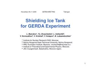
November 09÷11 2005 GERDA MEETING Tübingen Shielding Ice Tank for GERDA Experiment L. Bezrukov 1 , Yu. Dvoychenko 2 , L. Inzhechik 3 , V. Kornoukhov 4 , V. Krishtal 5 , V. Kulepov 2 , B. Lubsandorzhiev 1 1) Institute for Nuclear Research RAS, Moscow;

E N D
November 09÷11 2005GERDA MEETING Tübingen Shielding Ice Tank for GERDA Experiment L. Bezrukov1, Yu. Dvoychenko2, L. Inzhechik3, V. Kornoukhov4, V. Krishtal5, V. Kulepov2, B. Lubsandorzhiev1 1) Institute for Nuclear Research RAS, Moscow; 2) Nizhny Novgorod State Technical University, Nizhny Novgorod; 3) RRC Kurchatov Institute, Moscow, <inzhechik@imp.kiae.ru>; 4) Institute of Theoretical and Experimental Physics, Moscow; 5) JSC Cryogenmash, Balashykha, Moscow region.
Vertical cut through the center of the experiment Fig. 7 GERDA Progress Report to the LNGS Scientific Committee. Version 0.3
Safety problems Liquid water surrounding the cryostat. Intensive (catastrophic) boiling of cryo-liquid can take place in the case of its leakage. Water convection accelerates the heat supply. Double function of outer wall of the cryostat — it is both outer vacuum envelope and inner wall of the water tank. It undergoes additional outer water hydrostatical pressure up to 0.6 atm in the bottom of the cryostat. Thus, maximal pressure load reaches 1.6 atm. for this wall (to the point: inner vacuum cryostat wall is under the same pressure). Big volume of cryo-liquid (40 m3) and big volume of liquid water (650 m3)— aggravates possible consequences of an accident of destruction of the envelopes.
5. Cooling contour 1 INPUT -20ºC Cooling liquid OUTPUT -10ºC 2 3 6.Third wall Cu 4 Cuthird wall. Ice instead water in the shielding tank Fig. 5. Ice tank with the third wall inside ice massif. 1 — ice (−10º C); 2 — Dewar for cryo-liquid; 3 — non-hermetic foam thermo-insulation; 4 — photo-multiplayer; 5 — cooling contour (spiral pipes); 6 — non-hermetic third wall assembled from copper sections.
Ice provides radical improvement of safety: • The outer ice tank in itself is not a source of danger in contrast to water tank — a spilling out of big volume of water can take place after destruction of its outer wall. • Direct contact of the cryo-liquid with solid ice is not followed by an explosive boiling. • The flow of heat supplied by massive solid ice can be calculated. • Ice massif is an additional thick solid wall surrounding the cryostat. It prevents intensive leakage of cryo-liquid out in the case of destruction of other inner envelopes. • The 3-rd wall can be non-hermetic: assembled from sections without welding. • Listed points ensure impossibility of “domino” scenario • Disadvantages of the ice are: • Density of ice is 10 % less than density of water. • Necessity of the thermo-insulation of the tank and of refrigerator system.
Filling of ice tank For freezing 650 tons of water (q=6013 J/mol, cp=75.3 J/(mol·K) at the initial temperature of 20ºC the energy of ≈2.7·1011 J must be taken away. It takes ≈65 d if the freezing power of the refrigerator machine equals to 50 kWt. Assembling from bricks.The rate of assembling is limited by productivity of frizzing machine(s) and by productivity of manual assembling procedure. Disadvantage — there are unavoidable gaps between bricks. However, it is possible to fill the gaps by water during the assembling. The bricks from pure ice provide the diffusion transparency of the massif and good operation of Cherenkov veto system. Freezing of a water layer.The typical velocity of freezing by this well-known technology equals to 30 mm per day at −10ºC and up to 70 mm/d at −20ºC. Inside the vessel with cooled walls (−20ºC) and ventilation it takes not more than 65 days to fill the ice tank with height of 9 m.
Cryo-liquid T0 = 77 K Solid ice semi-space infinite to the right T1 = −10º C Heat flow Initial conditions, t = 0: T(x=0) = T0; T(x>0) = T1 Boundary conditions, t > 0: T(x=0) = T0 T(x=∞) = T1 0 X Step function Upper limit for heat flow from ice into the cryostat Non-stationary thermo-conductivity equation: Where: T — ice temperature; λ — ice thermo-conductivity; ρ — ice density; cv—ice specific heat. A decision for this well-known case:
4 2 3 1 Upper limit for heat flow from ice into the cryostat It is assumed that the ice properties do not depend on temperature. To evaluate the flow limit the maximal figures are used: λ = 5 Wt/(m·K); ρ = 920 kg/m3; cv = 2.2 kJ/(kg·K) For liquid N2 specific heat of evaporation q = 5.59 kJ/mol, V(1 g mol) = 22.4 liters For ice at 77 K 1 — velocity of boiling of LN2 contacting with 1 m2 of surface of ice with initial temperature −10ºC in m3 per second; 2 — integral volume of gas evaporated from beginning of the contact; 3 — constant boiling velocity during first second; 4 — integral volume of evaporated gas for more realistic scenario
Ice is a good media for Cherenkov veto • The non-uniformity of ice is not a disadvantage due to high transparency. Diffused scattering of light inside of optically non-homogeneous ice (bubbles, cracks, swells) is not followed by substantial absorption. • Ice Cherenkov media made initially from pure ice does not need in additional purification during the long-term operation of the experiment. • There is no problem to deploy photomultiplier detector into ice. ≈ 1000 PMTs are currently being used in the AMANDA experiment in the Antarctica in ice at the depth of more than 1 km, for example. PMT Optical Modules used for AMANDA
5. Cooling contour 7. Free space between ice and cryostat 1 INPUT -20ºC Cooling liquid OUTPUT -10ºC 2 Fig. 5. Ice tank with the third wall inside ice massif. 1 — ice (−10º C); 2 — Dewar for cryo-liquid; 3 — non-hermetic foam thermo-insulation; 4 — photo-multiplayer; 5 — cooling contour (spiral pipes); 6 — ice third wall; 7 — free space between ice and the cryostat. 3 6.Third wall Ice 4 Ice tank with the ICE third wall
Laboratory experiments Deformation velocity, 1/sec Deformation velocity, 1/year Nature measurements Stress (pressure), bar (≈1.02 kgf/cm2) Dependence of deformation on shift stress for poly-crystal ice for different temperatures (ºC)[Badd & Raddok, 1971] Ice creep deformation The ice under pressure is a plastic material — Recollect moving glaciers!
Deformation of the ice cylinder of height of 10 m with a through axial aperture For 10 years at -10ºC the radius of the aperture in the bottom of the cylinder will decrease for 0.3 m
5. Cooling contour 1 INPUT -20ºC Cooling liquid OUTPUT -10ºC 2 3 6.Third wall ICE 4 Ice tank with the reinforced ICE as a third wall 8. Suspending rope 7. Reinforcing Cu elements 9. Anchkor rope Fig. 5. Ice tank with the third wall inside ice massif. 1 — ice (−10º C); 2 — Dewar for cryo-liquid; 3 — non-hermetic foam thermo-insulation; 4 — photo-multiplayer; 5 — cooling contour (spiral pipes); 6 — ICE third wall; 7 — reinforcing Cu elements; 8, 9 — ropes for fixation of the Cu reinforcing elements.
LOW BACKGROUND CONCRETE ICE WATER CRYOSTAT 0.5 m 2.1 m External shielding from low background concrete Attenuation of γ radiation by water. Dosimetry data for wide γ-bunch
Cryo-liquid Ice bricks Replacement of a grater part of cryo-liquid with ice Cryostat filled by cryo-liquid (10% of its volume) and ice (90%). The ice brick variant.
Conclusions • To meet the safety requirements of the “GERDA Experiment. Second-opinion on risk assessment” and to improve the general experiment safety • it is proposed: • To use ice tank instead of water one to shield GERDA detector cryostat against outer gammas and neutrons. • The solid ice environment of the cryostat gives a possibility to predict the scenario of an accident of cryo-liquid leakage. • In the case of the ice shielding the copper «third wall» could be non-hermetic and could be assembled from parts without welding. • The best solution seems to be the “third wall” made from the ice reinforced by the Cu elements. • To use an additional outer wall made from low background concrete. • The concrete outer wall is an additional safety case. • The decreasing of total mass of the super pure water makes cheaper the setup. • The outer shielding laid from concrete blocks, can be disassembled easily after the finish of the GERDA experiment • To replace a greater part of the cryo-liquid with ice inside the Dewar.It reduces toa marked degree the scale of dangerous consequences of a destruction of the envelopes of cryo-liquid.