Download

1 / 41
410 likes | 561 Vues
Outline for Today. Objective Power-aware memory Announcements. Memory System Power Consumption. Laptop Power Budget 9 Watt Processor. Handheld Power Budget 1 Watt Processor. Laptop: memory is small percentage of total power budget Handheld: low power processor, memory is more important.

E N D
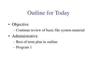
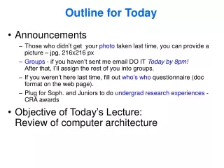
Outline for Today • Objective • Power-aware memory • Announcements
Memory System Power Consumption Laptop Power Budget 9 Watt Processor Handheld Power Budget 1 Watt Processor • Laptop: memory is small percentage of total power budget • Handheld: low power processor, memory is more important
Opportunity: Power Aware DRAM Read/Write Transaction • Multiple power states • Fast access, high power • Low power, slow access • New take on memory hierarchy • How to exploit opportunity? RambusRDRAM Power States Active 300mW +6000 ns +6 ns Power Down 3mW Standby 180mW +60 ns Nap 30mW
Each chip can be independently put into appropriate power mode Number of chips at each “level” of the hierarchy can vary dynamically. Policy choices initial page placement in an “appropriate” chip dynamic movement of page from one chip to another transitioning of power state of chip containing page RDRAM as a Memory Hierarchy Active Active Nap
RAMBUS RDRAM Main Memory Design Part of Cache Block CPU/$ • Single RDRAM chip provides high bandwidth per access • Novel signaling scheme transfers multiple bits on one wire • Many internal banks: many requests to one chip • Energy implication: Activate only one chip to perform access at same high bandwidth as conventional design Chip 0 Chip 1 Chip 3 Chip 2 Active Power Down Standby
Conventional Main Memory Design Part of Cache Block • Multiple DRAM chips provide high bandwidth per access • Wide bus to processor • Few internal banks • Energy implication: Must activate all those chips to perform access at high bandwidth CPU/$ Chip 0 Chip 1 Chip 3 Chip 2 Active Active Active Active
Exploiting the Opportunity Interaction between power state model and access locality • How to manage the power state transitions? • Memory controller policies • Quantify benefits of power states • What role does software have? • Energy impact of allocation of data/text to memory.
Power-Aware DRAM Main Memory Design CPU/$ Software control • Properties of PA-DRAM allow us to access and control each chip individually • 2 dimensions to affect energy policy: HW controller / OS • Energy strategy: • Cluster accesses to already powered up chips • Interaction between power state transitions and data locality Page Mapping Allocation OS Hardware control ctrl ctrl ctrl Chip 0 Chip 1 Chip n-1 Power Down Active Standby
Power-Aware Virtual Memory Based On Context Switches Huang, Pillai, Shin, “Design and Implementation of Power-Aware Virtual Memory”, USENIX 03.
Basic Idea • Power state transitions under SW control (not HW controller) • Treated explicitly as memory hierarchy: a process’s active set of nodes is kept in higher power state • Size of active node set is kept small by grouping process’s pages in nodes together – “energy footprint” • Page mapping - viewed as NUMA layer for implementation • Active set of pages, ai, put on preferred nodes, ri • At context switch time, hide latency of transitioning • Transition the union of active sets of the next-to-run and likely next-after-that processes to standby (pre-charging) from nap • Overlap transitions with other context switch overhead
Power-Aware DRAM Main Memory Design CPU/$ Software control • Properties of PA-DRAM allow us to access and control each chip individually • 2 dimensions to affect energy policy: HW controller / OS • Energy strategy: • Cluster accesses to preferred memory nodes per process • OS triggered power state transitions on context switch Page Mapping Allocation OS Hardware control ctrl ctrl ctrl Chip 0 Chip 1 Chip n-1 Nap Active Standby
Rambus RDRAM Read/Write Transaction RambusRDRAM Power States Active 313mW +20 ns +3 ns Standby 225mW Power Down 7mW +22510 ns +20 ns Nap 11mW +225 ns
A node is active iff at least one page from the node is mapped into process i’s address space. Table maintained whenever page is mapped in or unmapped in kernel. Alternativesrejected due to overhead: Extra page faults Page table scans Overhead is onlyone incr/decrper mapping/unmapping op Determining Active Nodes
Implementation Details Problem: DLLs and files shared by multiple processes (buffer cache) become scattered all over memory with a straightforward assignment of incoming pages to process’s active nodes – large energy footprints afterall.
Implementation Details Solutions: • DLL Aggregation • Special case DLLs by allocating Sequential first-touch in low-numbered nodes • Migration • Kernal thread – kmigrated – running in background when system is idle (waking up every 3s) • Scans pages used by each process, migrating if conditions met • Private page not on • Shared page outside 3 ri
Evaluation Methodology • Linux implementation • Measurements/counts taken of events and energy results calculated (not measured) • Metric – energy used by memory (only). • Workloads – 3 mixes: light (editting, browsing, MP3), poweruser (light + kernel compile), multimedia (playing mpeg movie) • Platform – 16 nodes, 512MB of RDRAM • Not considered: DMA and kernel maintenance threads
Results • Base – standby when not accessing • On/Off –nap when system idle • PAVM
Results • PAVM • PAVMr1 - DLL aggregation • PAVMr2 – both DLL aggregation & migration
Conclusions • Multiprogramming environment. • Basic PAVM: save 34-89% energy of 16 node RDRAM • With optimizations: additional 20-50% • Works with other kinds of power-aware memory devices
Discussion: What about page replacement policies? Should (or how should) they be power-aware?
Related Work • Lebeck et al, ASPLOS 2000 – dynamic hardware controller policies and page placement • Fan et al • ISPLED 2001 • PACS 2002 • Delaluz et al, DAC 2002
tl->h th->l phigh phigh tbenefit plow ph->l pl->h constant Power State Transitioning completionof last request in run requests time gap Ideal case:Assume we wantno added latency (th->l + tl->h + tbenefit ) * phigh > th->l * ph->l + tl->h * pl->h + tbenefit * plow
tbenefit > th->l * ph->l + tl->h * pl->h –(th->l + tl->h) * phigh (phigh – plow) Benefit Boundary gap m th->l + tl->h + tbenefit
Power State Transitioning completionof last request in run requests time gap th->l tl->h phigh phigh On demand case- adds latency oftransition back up plow ph->l pl->h
Power State Transitioning completionof last request in run requests time gap threshold th->l tl->h phigh phigh Threshold based- delays transition down ph->l plow pl->h
Dual-state HW Power State Policies access Active • All chips in one base state • Individual chip Active while pending requests • Return to base power state if no pending access No pending access access Standby/Nap/Powerdown Active Access Base Time
Quad-state HW Policies access access no access for Ta-s Active STBY • Downgrade state if no access for threshold time • Independent transitions based on access pattern to each chip • CompetitiveAnalysis • rent-to-buy • Active to nap 100’s of ns • Nap to PDN 10,000 ns no access for Ts-n access access PDN Nap no access for Tn-p Active STBY Nap Access PDN Time
Page Allocation and Power-Aware DRAM • Physical address determines which chip is accessed • Assume non-interleaved memory • Addresses 0 to N-1 to chip 0, N to 2N-1 to chip 1, etc. • Entire virtual memory page in one chip • Virtual memory page allocation influences chip-level locality CPU/$ Page Mapping Allocation OS Virtual Memory Page ctrl ctrl ctrl Chip 0 Chip 1 Chip n-1
Page Allocation Polices Virtual to Physical Page Mapping • Random Allocation – baseline policy • Pages spread across chips • Sequential First-Touch Allocation • Consolidate pages into minimal number of chips • One shot • Frequency-based Allocation • First-touch not always best • Allow (limited) movement after first-touch
Random Allocation Sequential Allocation Dual-state Hardware Quad-state Hardware The Design Space 1 Simple HW 2 Can the OS help? 2 state model 3 Sophisticated HW 4 Cooperative HW & SW 4 state model
Methodology • Metric: Energy*Delay Product • Avoid very slow solutions • Energy Consumption (DRAM only) • Processor & Cache affect runtime • Runtime doesn’t change much in most cases • 8KB page size • L1/L2 non-blocking caches • 256KB direct-mapped L2 • Qualitatively similar to 4-way associative L2 • Average power for transition from lower to higher state • Trace-driven and Execution-driven simulators
Methodology Continued • Trace-Driven Simulation • Windows NT personal productivity applications (Etch at Washington) • Simplified processor and memory model • Eight outstanding cache misses • Eight 32Mb chips, total 32MB, non-interleaved • Execution-Driven Simulation • SPEC benchmarks (subset of integer) • SimpleScalar w/ detailed RDRAM timing and power models • Sixteen outstanding cache misses • Eight 256Mb chips, total 256MB, non-interleaved
Dual-state + Random Allocation (SPEC) • All chips use same base state • Nap is best 60% to 85% reduction in E*D over full power • Simple HW provides good improvement
Benefits of Sequential Allocation (SPEC) • 10% to 30% additional improvement for dual-state nap • Some benefits due to cache effects
Random Allocation Sequential Allocation Dual-state Hardware Quad-state Hardware Results (Energy*Delay product) 10% to 30% improvement for nap. Base for future results Nap is best 60%-85% improvement 2 state model What about smarter HW? Smart HW and OS support? 4 state model
Quad-state HW (SPEC) • Base: Dual-state Nap Sequential Allocation • Thresholds: 0ns A->S; 750ns S->N; 375,000 N->P • Quad-state + Sequential 30% to 55% additional improvement over dual-state nap sequential • HW / SW Cooperation is important
Random Allocation Sequential Allocation Dual-state Hardware Quad-state Hardware Summary of Results (Energy*Delay product, RDRAM, ASPLOS00) Nap is best dual-state policy 60%-85% Additional 10% to 30% over Nap 2 state model Best Approach: 6% to 55% over dual-nap-seq, 80% to 99% over all active. Improvement not obvious, Could be equal to dual-state 4 state model
Conclusion • New DRAM technologies provide opportunity • Multiple power states • Simple hardware power mode management is effective • Cooperative hardware / software (OS page allocation) solution is best