Download
1 / 18
310 likes | 584 Vues
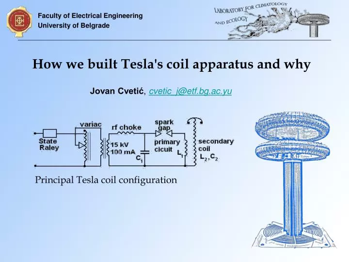
Faculty of Electrical Engineering University of Belgrade. How we built Tesla's coil apparatus and why. Jovan Cvetić , cvetic_j @ etf.bg.ac.yu. Principal Tesla coil configuration. Faculty of Electrical Engineering University of Belgrade. Tesla ’s patent. Faculty of Electrical Engineering

E N D
Faculty of Electrical Engineering University of Belgrade How we built Tesla's coil apparatus and why Jovan Cvetić, cvetic_j@etf.bg.ac.yu Principal Tesla coil configuration
Faculty of Electrical Engineering University of Belgrade Tesla’s patent
Faculty of Electrical Engineering University of Belgrade Tesla coil general properties: • High-voltage two-coil resonant transformer. • The coil is usually tuned by changing primary circuit inductance (3 to 10 turns) and the spark gap switching frequency. • Coupling between the coils is loose (0.1-0.2) • The maximum energy transferred to the secondary circuit is 50 to 80 percent of the energy initially stored in the primary capacitor.
Faculty of Electrical Engineering University of Belgrade Theory and Model (1) • According to Kirchoff laws:
Faculty of Electrical Engineering University of Belgrade Theory and Model (2) • Analytical solution: • Abbreviations
Faculty of Electrical Engineering University of Belgrade Secondary circuit (1) The secondary coil geometrical parameters used in calculations • The secondary coil inductance was measured using RLC meter at 1kHz and compared to semi-empirical Wheeler’s formula: Wheeler’s formula: mH Measured: Ls=45.5mH
Faculty of Electrical Engineering University of Belgrade Secondary circuit (2) • In order to lower resonant frequency of secondary circuit, the distance between the toroidal terminal and the top of the coil is varied. The following pictures are showing self resonant frequency, and top capacitance versus distance from the secondary coil • The geometrical parameters are chosen in such way that self-resonant frequency of secondary circuit is 107.8kHz
Faculty of Electrical Engineering University of Belgrade Secondary circuit (3) • The total capacitance consists of: • the coil self-capacitance Cs, and • the capacitance of toroidal top, Ct. SLIKA KOLA • The secondary self-capacitance: Cs=KD=17.8pF Medhurst’s formula: Cs=18pF Measured: • The top capacitance: Semi-empirical formula: pF • The total capacitance: Ctot=56pF Formula: Ctot=50pF Measured:
Faculty of Electrical Engineering University of Belgrade Secondary circuit (4) • The secondary resistance is measured by RLC meter at 1kHz giving Rs=15.5W The summary of secondary coil electrical parameters
Faculty of Electrical Engineering University of Belgrade Primary circuit (1) • Capacitance value is usually between0.05mF and 0.2mF. We chose 93.7nF, measured with RLC meter at 1kHz. • The shape of the coil is Archimedes spiral composed of 11 turns of 6mm copper pipe. • The coil inductance versus number of turns was measured with RLC meter at 1kHz . • Since the self-resonant frequency of secondary circuit is 107.8kHz, the optimal number and inductance of the primary coil turns are 5.5 and 28mH, respectively.
Faculty of Electrical Engineering University of Belgrade Primary circuit (2) • The measurement of the primary coil resistance, which varies significantly with frequency,is difficult. • The resistance was measured without secondary circuit using output waveforms of self-resonant dumped oscillations on impulse input. • The decay time is given with t=2L/R which yields R=0.6W at 100kHz.
Faculty of Electrical Engineering University of Belgrade Rotary spark gap
Faculty of Electrical Engineering University of Belgrade Coupling coefficient • The mutual inductance and coupling coefficient are measured for various positions and number of turns of primary coil. (from 3 to 11). • For the secondary self-resonant frequency of 107.8kHz and adopted number of turns Np=5.5 of primary coil, one obtains k=0.15 for coupling coefficient.
Faculty of Electrical Engineering University of Belgrade Output - simulation vs. measurement (time domain) • PSPICE simulated output voltage (right), compared to the measured signal acquisitioned via GPIB (down).
Faculty of Electrical Engineering University of Belgrade Output - simulation vs. measurement (FFT) • PSPICE simulated output voltage (right), compared to the measured signal acquisitioned via GPIB (down). =100.5kHz =116.9kHz
Faculty of Electrical Engineering University of Belgrade Conclusion • Although Tesla transformer should be analyzed using model with distributed parameters, this paper shows it can be successfully modeled with lumped element approach. • The results obtained from PSPICE and MatLab simulations are in good agreement with experimental data.
Faculty of Electrical Engineering University of Belgrade Applications • Rotary spark gap tuning • Development and simulation of Tesla coil twins • Electro dynamical modeling of rotary spark gap
Faculty of Electrical Engineering University of Belgrade Acknowledgments Professor Radivoje Đurić Professor Milan Savić Professor Acc. Aleksandar Marinčić Vladimir Malić Marko Cvejić and Milan Milošević – The Tesla coil EM modeling team Ivana Milovanović, Uroš Mitrović and Nebojša Malešević –The Rotary spark gap team