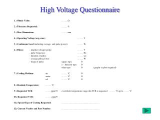
Liquid Argon TPC High Voltage Issues
Liquid Argon TPC High Voltage Issues. Voltage and current needs. Drift velocity sets the scale:. Choice of Electric field Strength. Choice of Electric field Strength Based on: “Reasonable drift time”

Liquid Argon TPC High Voltage Issues
E N D
Presentation Transcript
Liquid Argon TPC High Voltage Issues Hans Jostlein, Lar Workshop, November 4, 2004
Voltage and current needs Drift velocity sets the scale: Hans Jostlein, Lar Workshop, November 4, 2004
Choice of Electric field Strength • Choice of Electric field Strength Based on: • “Reasonable drift time” • Example: A field of 500 V/cm drifts electrons at 1.5 mm/microsec. It requires an electron lifetime of about 2 msec. This seems achievable • For a 3 m drift distance, the dwell time is 2 msec. • High Voltage Technology gets hard quickly at very large voltages. Hans Jostlein, Lar Workshop, November 4, 2004
Choice of Drift Field -- 2 • Technical limitations • Our example requires HV = (500 v/cm) * (300 cm) = 150 kV • If we were to try and double this, the total voltage would be 300 kV, which is quite challenging, while the dwell time would only go down to 1.5 msec. • In the other direction, if we were to halve the E-field to 250 V/cm, the dwell time would grow to 3 msec, not a big change from 2 msec, • but a huge voltage reduction, from 150kV to 75 kV, going from “achievable” to “routine”. Hans Jostlein, Lar Workshop, November 4, 2004
Voltage Regulation Requirements We pick an acceptable drift distance measurement tolerance of, say, 0.5 mm. For our example of 3m drift distance, this is 1/6000. The drift velocity must be constant at this level. The velocity versus field curve is not linear. We find that at 250 V/cm we must regulate the Voltage to 1/4300; For 500 V/cm we need to regulate to 1/2800; And for 1000 V/cm we need to regulate to 1/2400 Not a big effect ! Hans Jostlein, Lar Workshop, November 4, 2004
Current Flow Issues Filter and Leakage Currents: • Leakage currents are not well predicted, usually. • If we assume a leakage current of 100 microamp, as an example, then for the 500 V/cm case we are allowed a voltage variation of (150 kV) / 2800 = 54 Volts • Any series resistor in the HV filter must then be 540 kilo-ohms or lower. Electron drift current • The Physics current, due to ionization in tracks is small: • We assume about 55,000 electrons per cm of track. If we take an example of 3 events per msec, each with a track length of 10 m, we get an ionization current of 1.6 E11 electrons/sec, which is 26 micro-amps. Hans Jostlein, Lar Workshop, November 4, 2004
Noise Requirements Noise Requirements Noise on the HV supplies (Main drift HV and ancillary wire chamber bias supplies) couples capacitively into the wire chambers. Main Drift HV Supply • The noise of the main HV supply affects only the first induction plane. • The induced noise can be estimated from the noise fraction on the main drift field, induced into one wire. • For our prototype we estimate the capacitance from the Main HV into one wire as about 1 pF. A 1 Volt pulse on the HV will induce a charge of 1E-12 C, which corresponds to 6250 electrons. • The induced charge from a real track ionization is about (55,000 e) *(1 cm / wire spacing) = 27,500 electrons. Hans Jostlein, Lar Workshop, November 4, 2004
Signal to Noise • For a signal to HV noise ratio of 1%, we need to hold the HV ripple to 10 mV in the frequency region of interest. • Note that modern high frequency supplies often run in then 100 kHz range which is just about where we care the most. • A Filter is needed. Hans Jostlein, Lar Workshop, November 4, 2004
HV Filter Parameters • If we assume a supply with 10 Volt ripple, we need to reduce the ripple by a factor of 1000x. • Using an RC filter, we are further constrained by the maximum series resistor , due to leakage currents, of 540 kOhms (see above). • An RC filter is a voltage divider. • The noise is divided (approx) in the ratio (Series resistor / Capacitor impedance). • The capacitor impedance must be 1000 x smaller than the 450 kOhm series resistor, i.e. 450 Ohms. The capacitor’s impedance at the frequency of interest (100 kHz in our example) is R = C/(2*Pi*frequency). • W arrive at the required filter capacitance as C = 1/ (450 Ohm * 2*pi*100 kHz) =3.5 nF Hans Jostlein, Lar Workshop, November 4, 2004
Multi-Stage Filter • This is rather large and dangerous. • If we design the filter as a 3-stage RC filter, we end up with each stage having an 18 kOhm resistor and a 90 pF capacitor, which is much easier and safer. • The next slide shows is the filter box for the Flare prototype. • It is rather over-designed, but we had all the components lying around, so it was free. We also want to be able to deal with unknown noise sources such as lower frequency noise. Hans Jostlein, Lar Workshop, November 4, 2004
Flare Prototype Filter Box Hans Jostlein, Lar Workshop, November 4, 2004
Wire Chamber Bias Supplies • The field strength must increase after each wire plane by about 50% to collect all drift electrons without allowing them to reach the wires. • For a plane spacing of about a cm, these supplies are in the 0.5 to 2 kV range. • Common supplies designed for phototubes are quite suitable. • They are well regulated and come with voltage and current readback. • Even though the noise coupling capacitances are somewhat larger here, no problems are expected. • Feedthroughs are not extreme, but require care. Hans Jostlein, Lar Workshop, November 4, 2004
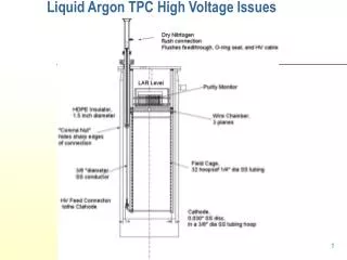
HV Feedthrough Issues The main drift HV feedthrough into the cold volume poses some interesting challenges: • --high voltages • --low breakdown voltage in Argon gas • --cold end • --gas seal • --prevent oxygen diffusion into the liquid argon • --Materials compatibility with argon purity Hans Jostlein, Lar Workshop, November 4, 2004
High Voltage Capability For the range up to 200 kV there is substantial experience , e.g. from particle separators. Standard coaxial cables exist. At the outer cable end, the outer jacket and wire shield is usually pulled back, while the polyethylene inner insulator continues for several inches. The assembly dips into a dielectric cavity, and makes contact with some spring arrangement. The wire shield is tied to the outer shield of the feed through assembly. At the Argon side, care must be taken not to expose any conductor to the gaseous Argon, which has a low electric field holding capability. The liquid Argon, by contrast , can hold of as much as 2 mega-volts per cm. Hans Jostlein, Lar Workshop, November 4, 2004
HV Feedthrough Design • Following Icarus practice, we make the feedthrough dielectric from a single HDPE rod that is long enough to dip well into the liquid Argon. • The gas seal consists, as it must, of an inner conductor seal and an outer dielectric seal. • Both seals rely on O-rings. • The inner conductor seal is located at the bottom of the outer cavity, where it stays warm, and is spring loaded against the dielectric with a set of Bellville washers that reside on the cold end, inside of a corona ball. • The outer dielectric seal is warm also, and is incorporated into a pair of modified CF flanges. • Both O-rings are continuously flushed with dry nitrogen (or dry Argon—yet to be decided) to prevent oxygen diffusion into the TPC argon.. Oxygen diffusion through Viton (fluorocarbon) and most other suitable materials is significant. Hans Jostlein, Lar Workshop, November 4, 2004
Flare HVFeed-through Hans Jostlein, Lar Workshop, November 4, 2004
Micro-Discharges • The Icarus experiment had problems with HV micro discharges inside cables and at connections. These discharges appear to be enabled by humidity. • Common cures include bathing the contacts in Fluorinert liquid and flushing with dry nitrogen. • We have adopted the latter. • A fitting on the main feedthrough will be supplied with dry nitrogen gas continuously. • A small passage hole channels some of the gas into the space surrounding outer O-ring, and the rest flushes the plug connection and flows into the outer jacket space of the HV cable. • A similar flush line will protect the HV filter and its supply and return cables. Hans Jostlein, Lar Workshop, November 4, 2004
HV Monitoring DC monitoring For value and stability of the DC voltages This is done by taking a small fraction of the voltage at the bottom of divider chains. It is particularly important to monitor the Voltage inside the TPC because it may have been reduced by unexpected leakage currents. One can imagine taking the test output from the cage divider and using it to regulate the DC supply. AC Monitoring Ac voltages are monitored from the last divider resistor. AC problems may include noise; drift; and micro discharges. Use an oscilloscope or a discharge detector, a la Icarus. Hans Jostlein, Lar Workshop, November 4, 2004
Current Monitoring Leakage currents can be a problem and an early indictor of developing HV problems. Currents are difficult to monitor in HV systems. The HV supply has often a ground-referenced current output for that purpose. Hans Jostlein, Lar Workshop, November 4, 2004
Electrical HV Safety These protective measures need to be taken: --- All devices are connected together with a good grounding cable, e.g. of size 1/2inch x 1/8 inch woven copper --- all HV devices have internal self-discharge resistors with a limited discharge time, e.g. one minute time constant or less ---all HV devices have a voltage divider output for monitoring their discharge status --all HV devices are fed through a high value, low power, resistor which limits any spark currents and functions a s a fuse in abnormal current conditions. The fuse for the TPC should be located outside the TPC, e.g. inside the filter box, for easy access. Hans Jostlein, Lar Workshop, November 4, 2004
Field Cage Design The drift field needs to be uniform to preserve the reconstructed event topology accurately. Typically the field needs to be shaped by a field cage, consisting of equipotential Loops. Icarus has built those from Stainless steel tubing, held with PEEK insulators to the vessel structure. Chains of resistors divide the Main drift HV into appropriate steps. They have also use sheets of printed circuit on fiberglass-epoxy for a smaller test chamber. For large detectors, stainless tubing seems to offer advantages. Hans Jostlein, Lar Workshop, November 4, 2004
Electric Field Uniformity Hans Jostlein, Lar Workshop, November 4, 2004
Electric Field Uniformity--2 • Electrons drift along filed lines, at right angle to equipotential surfaces. • It is convenient to have electrons drift exactly along straight paths. • Very close to the cage hoops there will be distortions. • Yet the electrons’ drift path is still deterministic, and can be calculated from the field map via the hoop geometry. If we know how far each electron has drifted, we can accurately determine its place of origin. Hans Jostlein, Lar Workshop, November 4, 2004
Electric Field Uniformity--3 • However, if we do not know the event time, we cannot do this and must reject the data very close to the hoops, except to gain topology information. • This is important information, e.g. when vetoing tracks entering from the outside. • In this case there is essentially no loss of fiducial volume. • We can use a very coarse cage structure, which is easier to build. Hans Jostlein, Lar Workshop, November 4, 2004
Resistors must meet several requirements: --be compatible with cooling --do not change resistance uncontrollably when cold --do not suffer damage from thermal cycles --be able to hold off the step voltage without internal discharges --be very reliable --be free of electronegative materials or contaminants Hans Jostlein, Lar Workshop, November 4, 2004
Resistors can be attached in different ways: --solder to lugs on the SS tubing --plug into holes using proper electrical contacts For redundancy on their larger detectors, Icarus has used four parallel resistor chains. Hans Jostlein, Lar Workshop, November 4, 2004