Alternator Functional Diagram
Alternator Functional Diagram. Alternator Functional Diagram. DC Current Applied to the Rotor. Alternator Functional Diagram. 3- Φ AC Output from the Stator. DC Current Applied to the Rotor. Alternator Functional Diagram. 3- Φ AC Output from the Stator. DC Current Applied to the Rotor.

Alternator Functional Diagram
E N D
Presentation Transcript
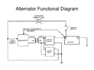
Alternator Functional Diagram DC Current Applied to the Rotor
Alternator Functional Diagram 3-ΦAC Output from the Stator DC Current Applied to the Rotor
Alternator Functional Diagram 3-ΦAC Output from the Stator DC Current Applied to the Rotor Six Output Diodes Two per Phase Full-Wave Rectifier
Alternator Functional Diagram 3-ΦAC Output from the Stator DC Current Applied to the Rotor Six Output Diodes Two per Phase Full-Wave Rectifier Three Diodes One per Phase Sample Battery Voltage
Alternator Functional Diagram 2 Inputs Regulator Controls the Amount of Field Current applied to the Rotor
Regulator Inputs • Control Voltage Input • Controls current through the Rotor • Field Current Supply • One input from the alternator via the Diode Trio • Second input from the battery via the warning lamp
Regulator Action • If the battery voltage drops, more current applied to the rotor, increasing the magnetic field strength, increasing the alternator voltage output. • If the battery voltage increases, less field current applied to the rotor, reducing the alternator voltage output.
Field Current Supply • Two Sources • Alternator via the diode trio • Battery via the warning lamp • Turn ignition ON, • Source of field current is the battery via the ignition switch and the warning lamp
Field Current Supply (continued) • After engine starts, • Alternator is up to speed, output of diode trio is fed back to the regulator and serves as the source of the field current. • Alternator is now self-sustaining
Warning Lamp • Turn ignition ON, • Current flows through warning lamp, transistors, and field coil to ground, causing the lamp to illuminate. • Alternator at full output, • Voltage from diode trio equals the battery voltage • equal voltage on both sides of lamp • lamp goes out.
Warning Lamp (continued) • If the alternator fails, • Voltage out of diode trio drops • Lamp illuminates from the battery voltage • If the battery fails, • Battery voltage drops • Lamp illuminates from the alternator voltage
Inside the Regulator IC1+Ic2 Ic2 Field Current Ic1 Sample Battery Voltage
Regulator Circuit • When battery voltage is OK, • D1 conducts • T2 conducts • Less current through T1 collector • T3 turns Off • Field current now reduced
Regulator Circuit (continued) • When battery voltage is low, • D1 is Off • T2 is Off • More current flows through T1collector • Transistor T3 turns On • Field current increases