Download
1 / 41
410 likes | 531 Vues
This article explores the significance of layered architectures in communication networks, emphasizing their role in supporting diverse services such as email, file transfer, and live broadcasting. It discusses the flexibility required for adapting to new technologies and applications, and introduces concepts like client/server relationships and the HTTP protocol. Through examples such as DNS queries and TCP interactions, the article illustrates how layered models simplify the design and maintenance of networks, enabling efficient communication while managing complexity in data exchange.

E N D
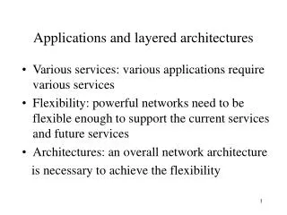
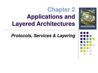
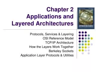
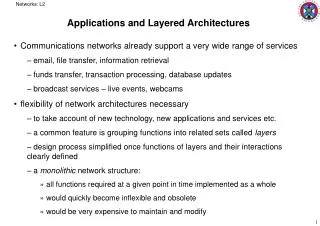
Networks: L2 Applications and Layered Architectures • Communications networks already support a very wide range of services • email, file transfer, information retrieval • funds transfer, transaction processing, database updates • broadcast services – live events, webcams • flexibility of network architectures necessary • to take account of new technology, new applications and services etc. • a common feature is grouping functions into related sets called layers • design process simplified once functions of layers and their interactions clearly defined • a monolithic network structure: • all functions required at a given point in time implemented as a whole • would quickly become inflexible and obsolete • would be very expensive to maintain and modify
Networks: L2 • Layering examples : • both use client/server relationships: • a server waits for incoming requests by listening to a port • server software known as a daemon • client processes make requests as required • servers provide responses to those requests • Example: Web browsing and the HyperText Transfer Protocol (HTTP) • HTTP specifies rules by which client and server interact to retrieve a document • see http://www.w3.org/Protocols for details • rules of request and response syntax defined • assumes client and server can exchange messages directly, peer-to-peer • the client must set up a two-way connection prior to the HTTP request HTTP client HTTP server Request Response
Networks: L2 • step 2 involves: • determining the IP address corresponding to the URL in the HTML file by making a DNS query • setting up a TCP connection with the WWW server on port 80, using an ephemeral port at the client end, used only for the duration of this connection • step 3 uses HTTP to request the document • specifying the GET method, the document and the protocol version in use • in step 5, the daemon sends a status line • and description of the information it will send • result code 200 indicates client request was successful • length of document and type • if request not successful, a failure message sent instead e.g. type 404 • in step 6, html file sent over TCP connection • browser interprets html and display the document • may initiate additional TCP connections for images etc. • and GET interactions
Networks: L2 • client and server are not directly connected • TCP provides the communication service to allow client and server to communicate • each HTTP process inserts message into a buffer and calls a TCP transmit function • TCP process then transmits buffer contents to other TCP process • in blocks known as segments • each segment contains port information in addition to HTTP message information • HTTP uses the service provided by TCP in an underlying layer • transfer of information between HTTP client and server is virtual • occurs indirectly via TCP • TCP itself uses and underlying layer i.e. the service provided by IP • simplification by use of layering
Networks: L2 HTTP server HTTP client Ephemeral Port No. Port 80 GET 80, # TCP TCP #, 80 STATUS
Networks: L2 • Example: DNS Query • message sent to DNS server to translate domain name to IP address • IP of local DNS server on Informatics network: 129.215.58.253 • DNS is a distributed database that resides on multiple machines on Internet • each machine maintains its own database and can be queried by other systems • see http://www.netfor2.com/dns.htm for more details • this protocol uses the User Datagram Protocol (UDP) instead of TCP • UDP client attaches a header to the user information to provide port information • port 53 for DNS • and encapsulates resulting block in an IP packet • see http://www.netfor2.com/udp.htm for more details • another peer-to-peer interaction using underlying layers • consider simple case where resolution takes place in first server • SQUERY : standard query • QNAME : name to be translated • QTYPE : A : translation to IP address
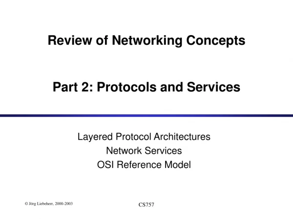
Networks: L2 n-PDUs n entity n entity • The OSI Reference Model (from ISO) • Open Systems Interconnection model • provides a framework for discussion of the overall communications process • layered communications protocols can be related to the OSI model • but none follow the model exactly • OSI partitions the process of communications into functions carried out in various layers • in each layer, a peer process converses with another on a different machine
Networks: L2 • processes at layer n are referred to as layer n entities • layer n entities communicate by exchanging protocol data units (PDUs) • each PDU contains a header containing protocol control information and user information in a service data unit (SDU) • behaviour of each layer n governed by its own conventions, a layer n protocol • for communication to take place, layer n+1 entities make use of layer n services • through a software port known as a service access point (SAP) n+1 entity n+1 entity n-SDU n-SDU n-SAP n-SAP n-SDU H n entity n entity n-SDU H n-PDU
Networks: L2 • information passed by layer n+1 to SAP is control information plus a PDU • the layer n+1 PDU is the layer n SDU • to which a layer n header is added for transfer at layer n • or the header is stripped off to supply the layer n SDU to the n+1 layer • in principle, the layer n protocol does not interpret or make use of information in the layer n+1 PDU • the layer n SDU is encapsulated in the layer n PDU • the user of a service provided by layer n is only interested in its correct execution • details of how this is achieved are irrelevant • Connection-oriented and connectionless services: • for a connection-oriented service: • a connection established between two layer n SAPs • may involve negotiating parameters, initialising sequence numbers etc. • n-SDUs transferred using the layer n protocol • the connection broken and resources released
Networks: L2 • a connectionless service does not require a connection setup • the control information passed from layer n+1 to layer n SAP must contain all the address information needed to transfer the SDU • the HTTP example used the connection-oriented TCP service • the DNS example used the connectionless UDP service • Confirmed and Unconfirmed services: • depending on whether the sender must be informed of the outcome • usually a connection-oriented service • Segmentation / Reassembly and Blocking / Unblocking services: • information transfers can be large or small, or continuous streams • many transmission systems have a bound on the individual block size • e.g. ethernet has a 1500 byte limit • a large layer n SDU can be segmented into multiple n-PDUs • and reassembled at the receiving end • small n-SDUs can be blocked into large units and unblocked at the other end • to make efficient use of layer n services
Networks: L2 Segmentation Reassembly n-SDU n-SDU n-PDU n-PDU n-PDU n-PDU n-PDU n-PDU Blocking Unblocking n-SDU n-SDU n-SDU n-SDU n-SDU n-SDU n-PDU n-PDU
Networks: L2 • The OSI Seven-Layer Reference Model: Application A Application B Application Layer Application Layer Presentation Layer Presentation Layer Session Layer Session Layer Transport Layer Transport Layer Communication Network Network Layer Network Layer Network Layer Network Layer Data Link Layer Data Link Layer Data Link Layer Data Link Layer Physical Layer Physical Layer Physical Layer Physical Layer Electrical and/or Optical Signals
Networks: L2 • Application layer • provides services frequently needed by applications • e.g. the HTTP application, FTP, Telnet, email etc. • Presentation layer • provides application with independence from differences in data representation • in principle, this should convert machine-dependent information at one end to a machine-independent form for transmission • and convert it, at the other end, to the form needed there • e.g. big-endian versus little-endian representation of bytes in a word • e.g. different character codes: ASCII versus Unicode • e.g. LSB first versus MSB first • Session layer • enhances a reliable transfer service by providing dialogue control and synchronisation facilities • e.g. NFS, Appletalk
Networks: L2 • Transport layer • responsible for the end-to-end transfer of messages between session entities • PDUs are called segments • can provide a variety of services: • a connection-oriented service could provide error-free message transport • including error detection and recovery, sequence and flow control • an unconfirmed connectionless service to transport individual messages • including address information for the session layer • segmentation / reassembly, and blocking / unblocking for the network layer • typically accessed through socket interfaces • can also be responsible for setting up and releasing network connections • could multiplex multiple transport layer connections into one network connection • could split a transport layer connection over several network layer connections • Top four layers involve peer-to-peer processes across the network; lower three layers involve peer-to-peer processes across individual hops
Networks: L2 • Network layer • transfer of data in packets across the network • routing • requires cooperation between network nodes • different schemes and protocols used in networks and in internetworks • between network packet switches and between internetwork gateways • also congestion control • e.g. IP • Data Link layer • transfer of frames directly between two nodes • adds framing information to delineate frame boundaries • inserts control and address information in a header • check bits in trailer to enable recovery from transmission errors • designed to include LAN functions • e.g. HDLC, PPP, FDDI, ATM
Networks: L2 • Physical layer • transfer of bits over a physical channel e.g. wire, fibre etc. • bit representations, voltage levels, signal durations • mechanical aspects : plugs and sockets • Each layer adds a header and possibly a trailer to the SDU is accepts from the layer above • ISO objective also to specify the protocols used in the various layers • overtaken by events when TCP/IP developed by Berkeley as part of UNIX
Networks: L2 Application B Application A data Application Layer Application Layer ah data Presentation Layer Presentation Layer ph data Session Layer Session Layer sh data Transport Layer Transport Layer th data Network Layer Network Layer nh data Data Link Layer Data Link Layer dh dt data Physical Layer Physical Layer bits
Networks: L2 Overview of TCP/IP Architecture • Communication across multiple diverse networks • evolved from Arpanet and other packet networks in 1983 • military funded research led to a premium on robustness • resilience to network failure • result is highly effective and the basis of the Internet • Two services offered by transport layer • Transmission Control Protocol (TCP) and User Datagram Protocol (UDP) • TCP offers a reliable connection-oriented transfer of a byte stream • error recovery, sequence order etc. • UDP offers best-effort connectionless transfer of individual messages • no error recovery or flow control
Networks: L2 Application Layer Application Layer Transport Layer Transport Layer Internet Layer Internet Layer Network Interface Network Interface • Network architecture consists of four layers • application layer covers top three OSI layers • e.g. HTTP, FTP etc. • has the option of bypassing intermediate layers • Internet layer • corresponds to OSI network layer • handles transfers across multiple networks through use of routers and gateways • provides a best-effort connectionless packet transfer service
Networks: L2 Application Transport Router/Gateway Application Internet Transport Network Interface Internet Internet Network Interface Network Interface Network 1 Network 2 • packets are exchanged between routers without connection setup • routed independently • may traverse different paths from source to destination • also called datagrams • connectionless transfer provides robustness • packets routed around points of network failure • gateways may discard packets when congestion occurs • responsibility for recovery passed up to the transport layer
Networks: L2 • Network Interface layer • corresponds to OSI Data Link and Physical layers • concerned with protocols that access intermediate networks • each IP packet is encapsulated into an appropriate packet for whatever intermediate network requires • interfaces available for various specific network types • X25, ethernet, token ring, ATM etc. • packet recovered at exit point from intermediate network • clear separation of internet layer from technology-dependent network interface layer • intermediate network technology transparent to TCP/IP user
Networks: L2 HTTP RTP SMTP DNS TCP UDP IP Network Interface Network Interface Network Interface • Some protocols of the TCP/IP suite: • all protocols access the network through IP • provides independence from underlying network technologies • multiple technologies can happily coexist in a network • IP complemented by other protocols • Internet Control Message Protocol (ICMP) • Address Resolution Protocol (ARP), Reverse Address Resolution (RARP) etc. • e.g. ethernet MAC address to IP address and back
Networks: L2 (1,1) (2,1) • Example: • a server plus a local workstation and a remote PC connected via a router • each host has at least one globally unique IP address • a network ID and a host ID • network ID obtained from authorised organisations such as NOMINET, the UK domain name registry • they also handle disputes over domain name ownership • simplified form: (network, host) • network interface cards (NICs) have physical addresses • every ethernet card has unique medium access control (MAC) address • 48 bits structured to include a manufacturer code (2,2) router s PPP (1,3) r w Ethernet (1,2)
Networks: L2 • more than one IP address if attached to two or more networks • the IP relates to the interface • a router has several interfaces and IP addresses • example has two networks: • the IP handler process in each host maintains a routing table • a routing address kept for every IP address it knows about • e.g. a physical ethernet MAC address • knows where to send packets for any IP address • or to a router by default Server PC HTTP HTTP TCP Router TCP IP IP IP Net Interface Net Interface Net Interface Ethernet PPP
Networks: L2 • e.g. workstation wants to send an IP datagram to the server • IP datagram contains destination and source IP address in the packet header • IP handler looks up destination IP address in its routing tables • finds server is directly connected via ethernet and knows the MAC address • IP datagram passed to Ethernet device driver • Ethernet driver prepares an ethernet frame: • protocol type field because ethernet may be passing non-IP packets also • Ethernet frame broadcast over the ethernet • server’s interface card recognises the destination MAC address as its own • server captures the frame • sees the IP type flag and passes the packet to the IP handler IP Header Header contains source and destination physical addresses; network protocol type Frame Check Sequence Ethernet Header
Networks: L2 • e.g. server wants to send a datagram to the remote PC • assume server knows IP address of PC • assume PC’s complete IP address not found in server’s routing tables • checks whether routing table contains network address part of PC’s IP address • if not, searches its routing table for a default router to be used when no other entries are found • assume it finds (1,3) as the router’s address • the IP datagram is passed to the ethernet driver which prepares a frame • frame contains destination and source physical addresses but IP datagram in the frame contains the destination IP address of the PC • the frame is broadcast over the ethernet • router picks up the frame and passes the datagram to its IP handler • IP handler in router sees that datagram not for itself but needs to be routed on • assume router finds PC at (2,2) is directly connected via a PPP link • router encapsulates datagram in a PPP frame and sends it via its PPP handler • no address information since this link is Point-to Point • PPP handler at PC receives frame, checks protocol type and passes it to its IP handler
Networks: L2 • e.g. consider a browser application • suppose PC user has clicked on a Web link to a document held on the server • assume that a TCP connection has already been established between the PC and the server • the HTTP request message GET is passed to the TCP layer • TCP handler encapsulates it into a TCP segment • containing an ephemeral port number and port 80 for the web server • TCP segment passed to IP layer which encapsulates it into an IP packet • IP packet contains destination IP address (1,1) and source (2,2) • header contains protocol type field indicating TCP • IP packet encapsulated into a PPP frame and sent to router • router forwards datagram to server over ethernet • server captures ethernet frame, extracts the IP frame and passes it to its IP handler • IP handler sees TCP flag, extracts TCP segment and passes it to its TCP handler • TCP handler sees port 80 and passes message to HTTP handler
Networks: L2 HTTP Request Header contains source and destination port numbers TCP Header Header contains source and destination IP addresses; transport protocol type IP Header Header contains source and destination physical addresses; network protocol type Frame Check Sequence Ethernet Header
Networks: L2 • all users use server’s port 80 • how does server know which connection message comes from? • the source port number, source IP address, and protocol type together define the socket address of the sender • similarly the socket address of the destination server • both together define a connection between user HTTP handler and server HTTP handler • in Unix/Linux, using the Berkeley Socket API • server creates a socket on which to listen for requests • when the TCP connection has been accepted, a new unique socket ID is used
Networks: L2 socket interface socket interface Application 1 Application 2 user user kernel kernel Socket Socket Underlying communication Protocols Underlying communication Protocols Communications network
Networks: L2 • The Berkeley Socket API • a socket is a communication end-point • once a TCP-socket connection between two processes is made, end-points made to act like ordinary files, using read() and write() system calls • creating a socket : • sd = socket ( family, type, protocol ); • binding to a local address : • bind ( sd, IP address, addrlen ); // address includes port number • connection by client process : • connect ( sd, IP address, addrlen ); // servers IP address • server listens for client connection requests : • listen ( sd, queuelen ); // number of requests that can be queued • and accepts the request : • newsd = accept ( sd, IP address, addrlen ); • accept() normally blocks if no client process waiting to establish a connection • can be made non-blocking for server to enquire whether any clients waiting
Networks: L2 Server socket() bind() listen() Client accept() socket() blocks until server receives a connect request from client connect negotiation connect() data write() read() data write() read() close() close()
Networks: L2 // Server-side socket demo progam#include <fcntl.h>#include <linux/socket.h>#include <linux/in.h>#include <errno.h>void close_socket(int sd) {int cs; if ((cs = close(sd)) < 0) { printf(“close socket failed: %s\n”, strerror(errno)); exit(1); }}#define SERVER (129<<24 | 215<<16 | 58<<8 | 7)#define MESSAGELEN 1024#define SERVER_PORT 5000void main() {int ssd, csd;struct sockaddr_in server, client;int sockaddrlen, clientlen, ca;char message[MESSAGELEN];int messagelen; sockaddrlen = sizeof(struct sockaddr_in);
Networks: L2 // create socket if ((ssd = socket (AF_NET, SOCK_STREAM, 0)) < 0) { printf(“socket create failed: %s\n”, strerror(errno)); exit(1): } else printf(server socket created, ssd = %d\n”, ssd); // bind socket to me server.sin_family = AF_INET; server.sin_port = htons(SERVER_PORT); // big/little-endian conversion server.sin_addr.s_addr = htonl(SERVER); bzero(&server.sin_zero, 8); if (bind(ssd, (struct sockaddr *) &server, sockaddrlen) < 0) { printf(“server bind failed: %s\n”, strerror(errno)); exit(1): } // listen on my socket for clients if (listen(ssd, 1) < 0) { printf(“listen failed: %s\n”, strerror(errno)); close_socket(ssd); exit(1); } // make socket non-blocking fcntl(ssd, F_SETFL, fcntl(ssd, F_GETFL) | O_NDELAY);
Networks: L2 // accept a client (non-blocking) clientlen = sockaddrlen; while ((csd = accept(ssd, &client, &clientlen)) < 0) { if (errno == EAGAIN) { printf(“no client yet\n”); sleep(1); // wait a sec } else { printf(“accept failed: %s\n”, strerror(errno)); close_socker(ssd); exit(1); } ca = ntohl(client.sin_addr.s_addr); printf(“client accepted, csd = %d, IP = %d.%d.%d.%d\n”, csd, (ca>>24)&255, (ca>>16)&255, (ca>>8)&255, ca&255); // send message to client sprintf(message, “Server calling client : hi!\n”); messagelen - strlen(message)+1; if (write(csd, message, messagelen) != messagelen) { printf(write failed\n”); close_socket(ssd); exit(1); } else printf(“message sent to client\n”); // receive message from client if (read(csd, message, MESSAGELEN) < 0) { if (errno == EAGAIN) {
Networks: L2 printf(“no client message yet\n”); sleep(1); } else { printf(“read failed: %s\n”, strerror(errno)); close_socket(ssd); exit(1); } printf(“client message was:\n%s”, message); close_socket(ssd);}
Networks: L2 // Client-side socket demo program#include <fcntl.h>#include <linux/socket.h>#include <linux/in.h>#include <errno.h>void close_socket(int sd) {int cs; if ((cs = close(sd)) < 0) { printf(“close socket failed: %s\n”, strerror(errno)); exit(1); }}#define SERVER (129<<24 | 215<<16 | 58<<8 | 7)#define MESSAGELEN 1024#define SERVER_PORT 5000void main() {int ssd, csd;struct sockaddr_in server, client;int sockaddrlen, clientlen, ca;char message[MESSAGELEN];int messagelen; sockaddrlen = sizeof(struct sockaddr_in);
Networks: L2 // server address server.sin_family = AF_INET; server.sin_port = htons(SERVER_PORT); server.sin_addr.s_addr = htonl(SERVER); for (;;) { //create socket if ((csd = socket(AF_INET, SOCK_STREAM, 0)) < 0) { printf(“client socket create failed: %s\n”, strerror(errno)); exit(1); } else prinf(“client socket create, csd = %d\n”, csd); // try to connect to server if (connect(csd, (struct sockaddr *) &server, sockaddrlen) < 0) { printf(“connect failed: %s\n”, strerror(errno)); // need to destroy socket before trying to connect again close_socket(csd); sleep(1); } else break; } printf(“connected to server\n”); // make socket non-blocking fcntl(csd, F_SETFL, fcntl(csd, F_GETFL) | O_NDELAY);
Networks: L2 // receive a message from server while (read(csd, message, MESSAGELEN) < 0) { if (errno == EAGAIN) { printf(“no server message yet\n”); sleep(1); } else { printf(“read failed: %s\n”, strerror(errno)); close_socket(csd); exit(1); } } printf(“server message was:\n%s”, message); // send a message to server sprintf(message, “Client calling server : ho!\n”); messagelen = strlen(message)+1; if (write(csd, message, messagelen) != messagelen) { printf(“write failed\n”); close_socket(csd); exit(1); } else printf(“message sent to server\n”); close_socket(csd);}