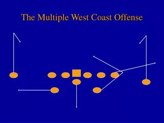
Computer Game : Basic
Computer Game : Basic. Computer Graphics and Its application 2D Coordinate Geometry 3.1 2D geometry -- points and polygons 3.2 Object transformation and Coordinates System transformation 3.3 2D Transformation -- Scaling, Translation, Rotation.

Computer Game : Basic
E N D
Presentation Transcript
Computer Game : Basic Computer Graphics and Its application 2D Coordinate Geometry 3.1 2D geometry -- points and polygons 3.2 Object transformation and Coordinates System transformation 3.3 2D Transformation -- Scaling, Translation, Rotation. 3.4 Homogeneous Coordinates 3.5 Composite 2D Transformation 3.6 Other Transformation -- Reflection (Mirror) and Shearing (Skip) 4. 2D Viewing Operations 4.1 Window-to-Viewport Mapping 4.2 2D Clipping 5. 3D Coordinate System 5.1 Coordinates System -- Right-handed and Left-Hand Coordinate system (a) 5.2 3D gemoetry -- points and polyhedra (a) 5.3 3D Transformation -- Scaling, Translation and Rotation. 5.4 Composite 3D Transformation -- Rotation about arbitrary Axis 5.5 Other Transformation -- Reflection and Shearing 6. 3D Viewing Operations 6.1 Projections -- Orthgraphic Projections and Perspective Projections(a 6.2 View Transformation 6.3 View Volume and Z-clipping 7. Visual Realism (Skip) 7.1 Rendering techniques 7.2 Hidden line removal algorithm 7.3 z-buffer algorithm 7.4 illumination and shading 7.5 Ray-tracing algorithm 7.6 Color and light
Computer Graphics vs. Pattern Recognition 3D arrows with 3D box Computer Graphics Pattern Recognition
Computer Graphics Application Some of today's most popular applications in computer graphics are : • Computer Game • Presentation Graphics • Electronic design and circuit layout • Mechanical design and drafting • Process Control • Data Analysis • 2D contour; 3D continuous mesh surface plot • air flow and fluid flow • 4D image; structural analysis of any properties • Simulation • Chemical and molecular analysis • User Interface • Animation • Art • Geometric and solid modeling
2D Geometry - points and polygons A point in 2D is represented by two real numbers (X,Y) Y X A line segment is represented by its two end points (X1,Y1) (X2,Y2), or a 2x2 matrix [ ] X1 Y1 X2 Y2 Y X
A polygon is represented by an list of points (X1,Y1), (X2,Y2), ..... (Xn,Yn) or a n x 2 matrix [ ] For example, a triangle is represent by [ ] X1 Y1 : : Xn Yn X1 Y1 X2 Y2 X3 Y3 Y X
Y (2,4) 2 (6,2) (2,2) 1 X 8 2 1 Object transformation and Coordinates System transformation Object transformation is different from the coordinates system transformation
Object Transformation Y Scale (1/2) about the origin X Y Translation (2,1) X Rotation (p/2) counter clock wise about the origin Y X
Coordinates system transformation Y* Scale (1/2) about the origin X* 2 3 1 Y Translation (2,1) X Y Rotation (p/2) counter clock wise about the origin X If not described explicitly, transformation always means object transformation
There are 3 "basic" transformations: (1) Translation (2) Scaling (3) Rotation A series of transformations can be combined (concatenated) into one. (1) Translation : T(Tx, Ty) 2D Translations Y (x',y') Ty (x,y) Tx X
Y Y (x',y') (x,y) X X (2) Scaling (about the origin) : S(Sx, Sy) • What about "Mirror Images"? • How do we avoid distortion? • What happens when the scale factor equal to zero? S(-2, -1)
(3) Rotation (about the origin • counterclockwise) : • x = R cos a • y = R sin a • x' = R cos(a + q) = R(cos a cos q - sin a sin q) • y' = R sin(a + q) = R(sin a cos q + cos a sinq) • So, • x ' = xcosq - ysinq • y ' = xsinq + ycosq Y (x',y') (x,y) q a X
Concatenation -- A series of transformations can be combined (concatenated) into one. Example: scaling about arbitrarypoint. 1. Translate so that point (a,b) becomes the temporary origin: x1 = x - a y1 = y - b 2. Scale to the correct size: x2 = Sx*x1y2 =Sy*y1 3. Translate again to restore the coordinates of (a,b): x3 = x2 + a y3 = y2 + b Y (x,y) (a,b) X
Algebraic representations for transformations are very limited: (1) A special procedure is need for each basic transformation and other known concatenated forms. (2) It is difficult to provide general transformation capabilities in algebraic form in the computer. (3) How can one find the inverse of a concatenated equation (to restore the original position, for example)?
Let the point (x,y) be a row vector [x y]: x' = ax + by and y' = cx + dy can be expressed in the matrix equation: [x' y'] = [x y] * [ ]2x2 Let P' = [x' y'] and P = [x y], this becomes the matrix equation: P' = P * T where P' =[x' y'] , P = [x y] , T = Consider three basic transformations, can we find a "T" for each? • What about translations? X'=X+Tx, Y'=Y+Ty No, P' =[x' y']=[x y] []+[Tx Ty]=P*T+Q • What about scaling? X'=Sx*X, Y'=Sy*Y Yes, P' =[x' y']=[x y] [] =P*T • What about rotation? x'=xcosq-ysinq, y'=xsinq+ycosq Yes, P' =[x' y']=[x y] [] a c b d [ ] 1 0 0 1 Sx 0 0 Sy cosq sinq -sinq cosq
Homogeneous Coordinates Let the point (x,y) be a row vector [x y 1]: x' = ax + by + e and y' = cx + dy + f can be expressed in the matrix equation: [x' y' 1] = [x y 1] [ ]3x3 This becomes the matrix equation P' = P * T where P'=[x' y' 1], P= [x y 1], T= [ ] Now, can we find a "T" for each transformation? • What about translations? Yes, T= [ ] • What about scaling? Yes, T= [ ] • What about rotation?Yes, T= [ ]
(x', y') = (0, 1) (x, y) = (1, 0) Y (2,2) A (4,1) C B (2,1) X To check, what should the matrix be if we: (1) translate by (0,0) ? P'=P*[ ]=P*[ ]=P (2) scale by (1,1) ? P'=P*[ ]=P*[ ]=P (3) rotate by 0 o ? P'=P*[ ]=P*[ ]=P (4) rotate by 90o ? P'=[x' y' 1]=[x y 1] [] =[1 0 1]*[]=[0 1 1] Draw the pictures and find the new vertices of the triangle for the following transformations (See the figure below) :
Y (2,2) A C (4,1) (2,1) B X Y (2,2) A C (4,1) (2,1) B X Y (2,2) A C (4,1) (2,1) B X (5) translate A by (2,1). (6) translate A by (-2,1). (7) scale A by (2,1). (8) scale A by (-1,1). Y (2,2) A C (4,1) (2,1) B X
Y (2,2) A C (4,1) (2,1) B X Y (2,2) A C (4,1) (2,1) B X Y (2,2) A C (4,1) (2,1) B X (9) scale A by (1,0). (10) scale A by (0,0). (11) rotate A by 0o. (12) rotate A by 90o . Y (2,2) A C (4,1) (2,1) B X
Y (x, y) (a,b) X Composite 2D Transformation Concatenation is easy now. Consider our scaling example: Example: We want to reduce the size or the box, without changing the position of point (a, b) Functional form and matrix form for each transformations: (1) translate: T(-a,-b) (2) scale : S(Sx,Sy) (3) translate: T(a,b)
Combining the matrix equations: P3 =P2* T (-a,-b)=(P1*S(Sx, Sy) )*T(a, b) =P*T(-a, -b)*S(Sx, Sy)*T(a, b) Multiply the matrices : Now, the matrix equation is : or, in algebraic form : Thus, a single 3x3 matrix can represent any combination of basic transformations in a simple form.
Window-to-viewport Mapping We can define a window as a rectangular region of the world coordinate space, and the viewport as a rectangular region of the device coordinate system. (1,1) (1,1) (0,1/2) VIEWPORT (Normalize) WINDOW (0,0) (-1,1) (1,1) (3/4,1) (0,1/2) (Distortion) WINDOW (-1,1) (1/4,0)
The problem is to "map" coordinates from the window units into the viewport units. Derive the mapping from (xw,yw) , a coordinate in the window, to (xv, yv), the corresponding point in the viewport: * Remove window coordinate system x1 = y1 = sxv sxw (xv,yv) syv syw (xw,yw) (cxw,cyw) (cxv,cyv) window viewport sxw syw (x1,y1) (cxw,cyw) window
* Convert units x2 = y2 = * Remove to viewport center xv = yv = so xv = yv = (1) What happens if the ratios sxv/sxw and syv/syw are not equal? (2) If you want a set of data in the window, how do you decide the size of the window? sxv (x2,y2) syv (cxv,cyv) viewport
(3) Can the window-to-viewport mappintg represented in matrix form?
Homework: Find the transformation matrix that will map points contained in a window whose lower left corner is at (2,2) and upper right corner is at (6,5) onto a viewport that has a lower left corner at (1/2, 1/2) and upper right corner at (1,1).
(80,80) * * (4) Derive the window to viewport mapping for viewports defined on devices which have the origin at the upper left of the screen, with the horizontal coordinate increasing right, and the vertical coordinate increasing down. y (100,100) h x v (100,100) (0,0) viewport window
2D Clipping The process of clipping decides which part, if any, of a primitive lies inside the window. The algorithms used for line clipping can be divided into two parts: (1) Check all the line segments and separate those that intersect the window boundary. (The curve is represented by a sequence of line segment) (2) Clip the line segments obtained from step 1 by calculating their intersections with the window boundaries. Clipping
E G F Ymax A D Ymin B C Xmin Xmax (1) How can we sure that a line segment is totally inside the window (such as A) ? Both endpoints of the segment fall within the boundaries. (2) How can we sure that a line segment is totally outside the window (such as E,F,G)? Let two endpoints are (x1,y1),(x2,y2) If ( max{x1,x2} < xmin or min{x1,x2} > xmax or max{y1,y2} < ymin or min{y1,y2} > ymax) then the line segment is totally outside the window. We introduce an efficient procedure, the Cohen-Sutherland algorithm, to check the intersection property and further clip the line segment if necessary.
Ymax Ymin Xmin Xmax Cohen-Sutherland Algorithm The 2D plane is divided into 9 regions. Each region is designated by a 4-bit (base 2) integer code. Each bit of the code is set to 1 (true) or 0 (false), starting with the left most one. The bits are assigned by the follow rule: bit 1 = 1 if the region is above the window. bit 2 = 1 if the region is below the window. bit 3 = 1 if the region is on the right of the window. bit 4 = 1 if the region is on the left of the window. (1001) (1000) (1010) (0001) (0000) (0010) (0001) (0100) (0110)
(1) Given a point (x,y), we would like to assign a "region code" to it by using Cohen-Suterlandalgorithm. In C this can be coded: code = 0 if (x < xmin) code = 1 if (x > xmax) code = 2 if (y < ymin) code += 4 if (y > ymax) code += 8 (2) According to the C code in (1), what code will be assigned if the point is on the boundary of the window? (0000) * 0 (3) How about the point on the line Xmax and not on the boundary of the window? (0100) or (1000) depending on y
(4) Draw precise picture for the partition of 2D plane according to the C code in (1). (Using solid line and dotted line) Let's consider the line clipping now. At first, the visibility of the line segment is determined as follows: (1) Visible -> Both endoint codes are (0000).
(2) Invisible -> Bitwise logical AND of the endpoint codes is not (0000). (3) Indeterminate -> Bitwise logical AND of the endpoint codes is (0000), but at least one of the endpoint does not have a (0000) code. On the third situation, the line endpoints are "pushed" towards the boundary line until the first or the second situation occurs. Ymax (0001) (0010) (0000) Ymin Xmin Xmax
The algorithm steps: 1. Calculate IC1 and IC2, the code of the two endpoints. 2. If (IC1 + IC2 .eq. 0) then "Visible". 3. If ( (IC1 .AND. IC2) .NE. 0) then "Invisible". 4. If ( IC1 .EQ. 0) then { Swap(IC1, IC2); Swap(X1,X2); Swap(Y1,Y2); } // At lease one point is outside the // viewport. Insure that point #1 is // one of the outside point. 5. Push endpoint #1 towards Xmin, Xmax, Ymin, or Ymax, depending on which region endpoint #1 occupies (via IC1). bit 1 = 1 toward Ymax bit 2 = 1 toward Ymin bit 3 = 1 toward Xmax bit 4 = 1 toward Xmin If endpoint #1 towards Ymax , then { Ymax = Y = X1 + t(Y2 - Y1), find t and calculate X = X1 + t(X2 - X1) } 6. Go To Step #1 above.
Example: Let Xmin = 2, Xmax = 8, Ymin = 2 and Ymax = 8, check the visibility of the following segments using the Cohen-Sutherland Algorithm and, if necessary, clip them against the appropriate window boundaries. Line AB: A(3,10) B(6,12) Line CD: C(4,1) D(10,6) B(6,12) A(3,10) Ymax =8 D(10,6) Ymin=2 C(4,1) Xmin=2 Xmax=8
Example: Let Xmin = 2, Xmax = 8, Ymin = 2 and Ymax = 8, check the visibility of the following segments using the Cohen-Sutherland Algorithm. Line AB: A(3,10) B(6,12) Line CD: C(4,1) D(10,6)
How will the algorithm handle these examples? (A) (B) (C) (D)
3D Coordinates System Right-handed Coordinates System X Y Y X Y X Left-handed Coordinates System X Y Y X X Y We will use vight-handed Coordinates System in our class.
5.2 3D Geometry Y (0,2,0) (0,0,0) X (3,0,0) (0,0,1) Z [ ] 0 0 0 3 0 0 0 2 0 0 0 1 We can use the way to represent 3D points and polyhedras as the way to represent 2D points and polygons. For example: represents a tetrahedron In homogenlous coordinates system represents the same tetrahedron
3D Transformations Let's discuss 3D transformations, going directly to matrix and functional forms: (1) Translation: [x' y' z' 1] = [x y z 1] * [] (2) Scaling: [x' y' z' 1] = [x y z 1] * [] (3) Rotation: • Rotating about X(Y or Z) does not change X's. • The value of Y' and Z' does not depend on X. • Row 4 and column 4 are always the same. • The problem is to locate sin, -sin and cos.
Y X Z [y' z' 1] = [y z 1] *[] cosq sinq0 -sinq cosq0 0 0 1 cosq sinq0 0 -sinq cosq0 0 0 0 1 0 0 0 0 1 [x' y' z' 1] = [x y z 1] *[] Y X Z (a) Rotate about Z: (b) Rotate about Y: Eye X Z
[z' x' 1] = [z x 1] *[] cosq sinq 0 -sinq cosq0 0 0 1 [x' z' 1] = [x z 1] *[] cosq -sinq 0 sinq cosq0 0 0 1 cosq 0 -sinq 0 0 1 0 0 sinq 0 cosq0 0 0 0 1 [x' y' z' 1] = [x y z 1] *[] Y X Z [y' z' 1] = [y z 1] *[] cosq sinq0 -sinq cosq0 0 0 1 1 0 0 0 0 cosq sinq0 0 -sinq cosq0 0 0 0 1 [x' y' z' 1] = [x y z 1] *[] (c) Rotate about X:
Y Y X X Z Z Y Y X X Z Z Homework: Rotate the block counterwisely p/2 degree about X, Y, Z axis respectively. Find new coordinate for each vertex. Rotate about X (0,3,0) (1,0,0) (0,0,2) Rotate about Y Rotate about Z
Projection Different eye position has different view.
After the projection, the distance between your eyes and the object vertices is unknown. With the help of hidden-line removal algorithm, you can know which vertex is closer to you.
Orthgraphic Parallel Projections vs. Perspective Projections Orthgraphic Parallel Projections: The center of projection is located at infinity and the projectors are prependicular to the projection plane . Perspective projections: The center of projection is located at a finite distance from the projection plane.
Y [x,y,z] [x,y,0] X Z Orthgraphic parallel Projection : Projection Plane : XY-Plane (Z=0) Projector : parallel to Z axis The Problem for finding projection point are simple: project to [ x y 0 ] [ x y z ] will
Perspective Projection : How to get a picture? (1) Freeze the scene. (2) Freeze you head (eyes). Perspective:
What information we need to project a picture into a projection plane via perspective projection? (1) eye position (2) object position (3) picture plane Anything else? (4) Up direction
Y X Z Up1 = [ ] Up2 = [ ] Up3 = [ ] 0 1 0 1 0 0 1 1 0