BORON CARBIDE BASED NEUTRON DETECTORS
BORON CARBIDE BASED NEUTRON DETECTORS. Ellen Day Manuel Diaz Andrew Harken Carl Lundstedt Brian Robertson Shireen Adenwalla University of Nebraska-Lincoln. Funded by the ONR, State of Nebraska and NASA. NEUTRON DETECTORS.

BORON CARBIDE BASED NEUTRON DETECTORS
E N D
Presentation Transcript
BORON CARBIDE BASED NEUTRON DETECTORS Ellen Day Manuel Diaz Andrew Harken Carl Lundstedt Brian Robertson Shireen Adenwalla University of Nebraska-Lincoln
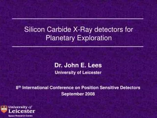
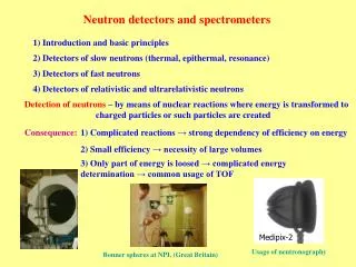
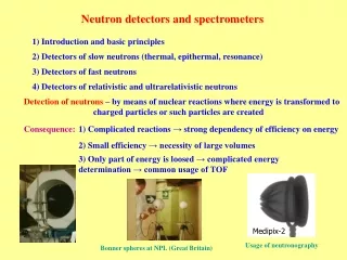
NEUTRON DETECTORS •Enforce nuclear safeguard agreements •Monitor reactors, nuclear stockpiles •Homeland security applications • Neutron scattering science at the new Spallation Neutron Source • Planetary and space exploration ALL SOLID STATE NEUTRON DETECTOR •Compact •Sturdy •Low power operation (even 0V!)
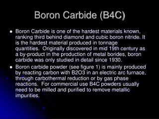
PROBLEMS Most materials have a tiny capture cross section for neutrons ENTER BORON CARBIDE •SEMICONDUCTING •LARGE capture cross section
SEMICONDUCTING FORM OF BORON CARBIDE 1990S PETER DOWBEN’S GROUP Boron Carbide on n-type Si Nickel doped boron carbide on p-type Si
DEOPSITION USING PLASMA-ENHANCED CHEMICAL VAPOR DEPOSITION (PECVD) Source Molecule C2B10H12 (ortho-carborane) : Closo-1,2-dicarbadodecaborane
Film Deposition Sublimated ortho-carborane molecules (70 ℃ ) with Ar gas (90 ℃) Chamber Temp : 90 C Pressure : 200 mTorr Gas Flow Rate : 10 sccm Deposition rate : 80 nm/10 min Ellen Day
FACT SHEET Capture c.s. for thermal neutrons =3850 barns 1/√E • 10B + n 7Li(0.84 MeV)+ 4He(1.47 MeV) +(0.48MeV) 94% 7Li (1.02 MeV )+ 4He( 1.78 MeV ) 6% •Abundance of 10B in naturally occurring B ~ 20% • All neutron data at KSU TRIGA tangential beam port ~ 10.6 n/cm2secW
10B Capture Cross Section ~ 1/√E
IS IT A TRUE SOLID STATE DEVICE? CONVERSION LAYER 1. B RICH LAYER CAPTURES NEUTRONS 2. CHARGE IS CAPTURED BY SEMICONDUCTING LAYER (DISTINCT FROM B RICH LAYER) TRUE SOLID STATE BOTH NEUTRON CAPTURE AND CHARGE CAPTURE OCCUR IN THE SAME MATERIAL IN THIS CASE BORON CARBIDE IMPLICATIONS FOR HIGHEST ATTAINABLE EFFICIENCY
Distinction between Different Devices • Path 1 • Path 2 Conversion layer Diode device
Simplified Model Comparisons with GEANT4 for Planar Conversion and All-B5C Detectors (Lundstedt et al, NIMPR, 2005)
Initial 1 mm B5C / Si heterojunction diodes (from 3” wafers with 276nm B5C) Up to > 3 x 10⁵ electrons / neutron
BC/Si diode BC on n-type Si Cr/Au contacts I-V curve of diode All BC device BC on Sapphire Cr/Au contacts Purely ohmic I-V
ALL BC RESISTIVE DEVICE =1.8 X 10⁶ -cm Vapp=7.5 V E field= 3 X 10⁴ V/cm dBC= 250 nm
MONTE CARLO SIMULATION FOR A 500 nm ALL BC DEVICE USING GEANT 4 NO SMEARING 30 KEV + 50 KEV SMEARING
Calc. efficiency≈Nx EXPERIMENTAL EFFICIENCY 5 X 10⁻⁵ CALCULATED EFFICIENCY 2 X 10⁻³ 1 40 = Incomplete charge collection-DISMAL FAILURE!
BUT…… Capacitance measurements indicate effective area only 10%of what we thought it was! Brings down incident neutron flux by factor of 10 NOW…. EXPERIMENTAL EFFICIENCY = 5 X 10⁻⁴ CALCULATED EFFICIENCY 2 X 10-3 =0.25 !!
Li 0.84 MeV He 1.47 MeV He 1.78 MeV BC/Si DIODE Vapp= 0 V d=230 nm E.E. Day et al J. Phys. D, 39, 2920 (2006)
PEAK POSITION vs. APPLIED BIAS Increase of ~ 60% in going from 0V to 3.15V INCREASED charge collection •higher E field, • larger depletion region (in Si)
EFFICIENCY 10% increase 1. Operation at 0V bias is both feasibleAND efficient 2. Increased bias DOES increase the charge collection significantly but not the efficiency. i.e. such a LARGE amount of charge is liberated per neutron capture event that even if only small fractions are collected they still provide a large enough signal above detector noise
CONCLUSIONS • Semiconducting boron carbide is a promising and versatile material for neutron detection. • All BC device WORKS! (albeit inefficiently) 3. Detected signal varies considerably depending on thickness of material, device types, device parameters 4. In order to understand the neutron generated signal, comparisons with modeling and/or simulations proves insightful. Future developments: Higher resistivity material Homojunction diodes Measurements of relevant semiconducting parameters Enriched boron carbide
Monte Carlo • Monte Carlo simulation toolkit used was GEANT 4.5.2. and GEANT 4.8.0. • GEANT handles the entire physical simulation. • Detector construction (Materials and geometry), neutron transport, capture cross sections etc… • GEANT tracks the ion energy loss as it travels through the material.
Simulation Assumptions • GEANT simulation assumptions • All the energy deposited is converted into electron hole pairs • All charges generated are collected by the electrodes • Boron carbide layer (B5C) constructed out of 19% 10B and 81% 11B natural occurrence • No electronic noise incorporated
Base Device • Device Construction • Thickness of Boron Carbide layer varied • 381μm Si layer. • Thermal neutron beam is incident normal to the Boron Carbide surface. • Capture cross section for 0.025eV neutron is 3840 barns.
Conversion Layer Diode 10 Million Neutrons Incident
500nm plus moderator • Device Construction • 500nm Boron Carbide layer • 381μm Si layer. • Moderator • H2O • Thickness varied • Neutron Energy • 100eV
Calorimeter • Measures the energy of particles by discrimination. • Neutrons with energy greater than their surroundings will lose energy by elastic scattering in the moderator.
Simplified Calorimeter • Device construction • 500nm Boron Carbide layer • 381μm Si layer • Moderator • H2O • 1.5cm • 4.0cm • Neutron energy • 100eV
Calorimeter Modification • Graphite Reflector added • 1.0 cm thick
Graphite Reflector Top Detector Bottom Detector ____ no moderator no reflector ____ graphite reflector above moderator ____ moderator no reflector
Conclusions • Monte Carlo modeling has proven successful in determining the expected spectra for novel neutron detectors. • Modeling has demonstrated that using a calorimeter incorporating boron carbide detectors can be effective as an energy discriminator.
ACKNOWLEDGEMENTS FUNDING Office of Naval Research N00014-04-1-0605 Nebraska Research Initiative NASA MIKE WHALEY TROY UNRUH For technical support in the TRIGA MARK II Nuclear Reactor Facility at the Kansas State University.
500 nm Conversion Layer BC with Additional smearing (eg incomplete charge collection)
Substrate Cleaning Acetone, Methanol, DN water Ar Plasma Etching Base Pressure : < 10-7 Torr Working Pressure : 200 mTorr RF Power : 30 Watt Ar Gas Flow Rate : 8 sccm Ar Gas Temperature : Ellen Day