L. Jenner, Liverpool University, Cockcroft Institute, Daresbury Laboratory, Warrington, U.K.
A STUDY OF EMITTANCE MEASUREMENT AT THE ILC. L. Jenner, Liverpool University, Cockcroft Institute, Daresbury Laboratory, Warrington, U.K. D.Angal-Kalinin, CCLRC,ASTeC, Cockcroft Institute, Daresbury Laboratory, Warrington, U.K.

L. Jenner, Liverpool University, Cockcroft Institute, Daresbury Laboratory, Warrington, U.K.
E N D
Presentation Transcript
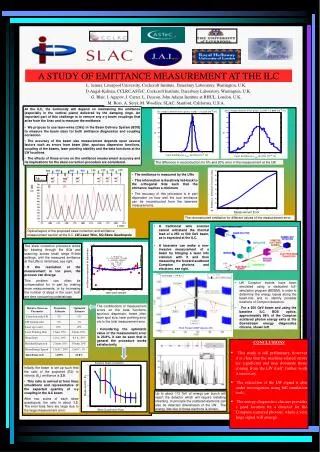
A STUDY OF EMITTANCE MEASUREMENT AT THE ILC L. Jenner, Liverpool University, Cockcroft Institute, Daresbury Laboratory, Warrington, U.K. D.Angal-Kalinin, CCLRC,ASTeC, Cockcroft Institute, Daresbury Laboratory, Warrington, U.K. G. Blair, I. Agapov, J. Carter, L. Deacon, John Adams Institute at RHUL, London, U.K. M. Ross, A. Seryi, M. Woodley, SLAC, Stanford, California, U.S.A. • At the ILC, the luminosity will depend on maintaining the emittance (especially in the vertical plane) delivered by the damping rings. An important part of this challenge is to remove any x-y beam couplings that arise from the linac and to measure the emittance. • We propose to use laser-wires (LWs) in the Beam Delivery System (BDS) to measure the beam sizes for both emittance diagnostics and coupling correction. • The accuracy of the beam size measurement depends upon several factors such as errors from beam jitter, spurious dispersion functions, coupling of the beams, laser pointing stability and the beta functions at the LW locations. • The effects of these errors on the emittance measurement accuracy and its implications for the skew correction procedure are considered. The difference in reconstruction for 5% and 20% error in the measurement at the LW. • The emittance is measured by the LWs • This information is iteratively fed-back to the orthogonal SQs such that the emittance reaches a minimum. • The accuracy of this procedure is in part dependent on how well the true emittance can be reconstructed from the laserwire measurements. Df x,y The reconstructed emittance for different values of the measurement error. • A traditional wire scanner cannot withstand the thermal load of a 250 or 500 GeV beam, as is expected at the ILC. • A laserwire can make a non-invasive measurement of a beam by bringing a laser into collision with it and then measuring the forward-scattered Compton photons and electrons, see right. Optical layout of the proposed skew correction and emittance measurement section at the ILC. LW-Laser Wire, SQ-Skew Quadrupole • The skew correction procedure works by iterating through the SQs and scanning across small range B-field settings, until the measured emittance at the LWs is minimised, see right. • If the resolution of the measurement is too poor, the process can diverge. • This problem can often be compensated for in part by making more measurements, or by increasing the number of steps in the scan; both are time consuming undertakings. • LW Compton events have been simulated using a dedicated full-simulation program (BDSIM), in order to determine the energy losses along the beam-line and to identify possible locations of Compton detectors. • For a 250 GeV beam and using the baseline ILC BDS optics, approximately 98% of the Compton scattered photon energy exits at the downstream energy diagnostics chicane, shown left. • The contributions of measurement errors on the beta functions, spurious dispersion, beam jitter, laser spot size, laser pointing error etc to the total measurement error. • Considering the optimistic value of the measurement error is 23.8%, it can be seen that in general the procedure works satisfactorily. • CONCLUSIONS • This study is still preliminary, however it is clear that the machine-related errors are significant and may dominate those coming from the LW itself; further work is necessary. • The extraction of the LW signal is also under investigation, using full simulation tools. • The energy-diagnostics chicane provides a good location for a detector for the Compton scattered photons, where a very large signal will emerge. • Initially the beam is set up such that the ratio of the projected (E2) to intrinsic (Ey) emittance is 3.8. • This ratio is arrived at from linac simulations and representative of the expected quantity of x-y coupling in the ILC beam. • After two scans of each skew quadrupole, the ratio is about 1.3. The error bars here are large due to the large measurement error. Up to about 113 TeV of energy per bunch will reach the detector which will require installing shielding. In principle the scattered electrons can also be detected downstream of the LW. The energy loss due to these electrons is shown.