Download
1 / 16
160 likes | 1.16k Vues
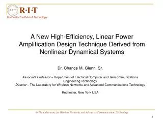
R I T. Rochester Institute of Technology. A New High-Efficiency, Linear Power Amplification Design Technique Derived from Nonlinear Dynamical Systems. Dr. Chance M. Glenn, Sr. Associate Professor – Department of Electrical Computer and Telecommunications Engineering Technology

E N D
R I T Rochester Institute of Technology A New High-Efficiency, Linear Power Amplification Design Technique Derived from Nonlinear Dynamical Systems Dr. Chance M. Glenn, Sr. Associate Professor – Department of Electrical Computer and Telecommunications Engineering Technology Director – The Laboratory for Wireless Networks and Advanced Communications Technology Rochester, New York USA © The Laboratory for Wireless Networks and Advanced Communications Technology
R I T Overview Rochester Institute of Technology • This talk describes the basis and implementation of a new concept in power amplifier design. • This work represents a collaborative effort between the Laboratory for Wireless Networks and Advanced Communications Technology at RIT, and Syncrodyne Systems Corporation. • The ongoing research effort has also been supported by DARPA, ARO, and MDA • The goal is the commercial application of this technology in various forms of wireless telecommunications. © The Laboratory for Wireless Networks and Advanced Communications Technology
R I T Chaotic Oscillator Input x(t) Output y(t) Coupling Control DC Power Adaptive Power Control & Output Stabilization Syncrodyne Power Amp Block Diagram Rochester Institute of Technology © The Laboratory for Wireless Networks and Advanced Communications Technology
R I T Chaotic Dynamics Rochester Institute of Technology • The heart of the Syncrodyne Power Amplifier is the chaotic oscillator • Chaos is a type of behavior that occurs in nonlinear systems. • While chaos tends to elude specific definition, there are properties that define its behavior: • Broad-band frequency spectra • Sensitivity to small changes • Tendency towards synchronization • Capable of efficient operation (nonlinearity) © The Laboratory for Wireless Networks and Advanced Communications Technology
R I T Vcc + L R Vc Q C Ve Re Ce + Vee Chaotic Dynamics Rochester Institute of Technology • A typical chaotic oscillator is the Colpitts system. • The Colpitts circuit is a typical circuit topology used in the engineering design of oscillators. Equations of motion: Circuit diagram: where © The Laboratory for Wireless Networks and Advanced Communications Technology
R I T Chaotic Dynamics Rochester Institute of Technology State-space plot: © The Laboratory for Wireless Networks and Advanced Communications Technology
The term Syncrodyne derives from the concept of amplification using synchronous dynamics. Dynamically matched devices are used which lock to a signal of similar dynamics. R I T Syncrodyne Amplification Rochester Institute of Technology The green (applied) and blue (output) signals in this schematic representation come together (synchronize) and the error (red) goes to zero rapidly when the input is coupled. © The Laboratory for Wireless Networks and Advanced Communications Technology
R I T Adaptive Nature of Synchronization Rochester Institute of Technology • We first reported that a chaotic system was adaptable, or conformed to, non-chaotic waveforms. • That is, a chaotic system, properly coupled, will take on the nature of an arbitrary waveform, depending on some conditions. • This realization was critical to the implementation of this technique on typical information bearing signal formats like GSM and CDMA. • We first showed this adaptive conformity using phase modulated sinusoidal waveforms coupled to a Colpitts oscillator operating in the chaotic regime. © The Laboratory for Wireless Networks and Advanced Communications Technology
R I T Syncrodyne Amplification Rochester Institute of Technology Spectral content of the generated GSM signal. Spectral content of the free-running chaotic oscillator. Coupling Spectral content of the amplified GSM waveform using the Syncrodyne Power Amplifier Series-3 prototype simulation. © The Laboratory for Wireless Networks and Advanced Communications Technology
R I T Syncrodyne Amplification Rochester Institute of Technology The extent and effectiveness of Synchronization depends on the factors below: • dc bias voltages of the source signal and the chaotic signal (Vsdc and Vcdc) • peak to peak voltage range of the two signals (Vsr and Vcr) • fundamental frequencies of the two signals • Value of coupling impedance in the coupling circuit The factors mentioned above need to be properly matched to obtain maximum amplification of the source signal. Increase in the extent of coupling would increase the gain and the efficiency of the signal produced. Vsdc Vcdc Vsr Vcr © The Laboratory for Wireless Networks and Advanced Communications Technology
R I T ADS Simulation Diagram Rochester Institute of Technology The power amplifier system comprises of the following components: • The dc power source (5 volts dc) – V_DC • The chaotic oscillator • The coupling network • The modulated input source (GSM modulation at 800 MHz) • The load impedance © The Laboratory for Wireless Networks and Advanced Communications Technology
R I T ADS Simulation Diagram Rochester Institute of Technology • The circuit has three ports, the functions are as below • Port1 – dc supply (input) • Port2 – Amplified signal (output) • Port3 – Modulated signal (input) • The other components are varied to obtain the desired output. • Sample values are shown in the figure. P1 P2 P3 © The Laboratory for Wireless Networks and Advanced Communications Technology
R I T Results Rochester Institute of Technology The system SPA-S3-C2-BJT-SYS2 was simulated and the results obtained are as shown below. Other such circuits were simulated and the results are have been tabulated in an excel sheet. Synchronized output signal © The Laboratory for Wireless Networks and Advanced Communications Technology
R I T Conclusions Rochester Institute of Technology • We’ve demonstrated Syncrodyne Power Amplification for GSM waveforms with PAE greater than 50% and gain approaching 20-dB • We are implementing new techniques that should allow us to push the performance levels higher. • The property of chaotic oscillators to adaptively conform to different waveform types is a key to this concept. • We are able to achieve linear power amplification utilizing a nonlinear device, thus benefiting from the high efficiency capable in nonlinear operation. • We intend to explore the benefit of this amplification concept in other technology settings. © The Laboratory for Wireless Networks and Advanced Communications Technology
R I T Goals Rochester Institute of Technology • Push the performance to PAE > 70%, gain > 30-dB • Implement Series-3 design in hardware • Design a SPA-S3 chip to meet commercial performance criteria • Develop commercially viable testbed for performance evaluation • Cultivate strategic partnerships for technology adoption. The Laboratory for Wireless Networks and Advanced Communications Technology
R I T References Rochester Institute of Technology [1] E. Ott, C. Grebogi, J. A. Yorke, Phys. Rev. Lett. 64, 1196 (1990). [2] S. Hayes, C. Grebogi, E. Ott, Phys. Rev. Lett. 70, 3031 (1993). [3] H. Dedieu, M.P. Kennedy, and M. Hasler, “Chaos shift keying; Modulation and demodulation of a chaotic carrier using self-synchronizing Chua’s circuit,” IEEE Transactions on Circuits and Systems I, vol. 40, pp. 634-642, 1993. [4] C. M. Glenn, S. Hayes, Weak Signal Detection by Small-Perturbation Control of Chaotic Orbits, 1996 IEEE-MTT Symposium Digest (June 1996). [5] L. M. Pecora and T. L. Carroll, Synchronization in Chaotic Systems, Phys. Rev. Lett. 64, 821 (1990). [6] C. M. Glenn, Synthesis of a Fully-Integrated Digital Signal Source for Communications from Chaotic Dynamics-based Oscillations, Doctoral Dissertation, The Johns Hopkins University, January 2003. [7] C. M. Glenn, High-Gain, High-Efficiency Power Amplification for PCS, International Symposium on Advanced Radio Technology Digest, March 2003. [8] S. Cicarelli, Development of a Digital Wireless Communication System for Security Sensor Applications, Defense Nuclear Agency (Jan 1998) [9] Francis Moon, Chaotic Vibrations, Wiley & Sons, New York, 1987. [10] Edward Ott, Chaos in Dynamical Systems, Cambridge Univ. Press, Canada, 1993. The Laboratory for Wireless Networks and Advanced Communications Technology